Flutter Boundary Characteristics
The preceding sections describe procedures for the determination of the flutter boundary in terms of altitude, speed, and Mach number. For a standard atmosphere, any two of these conditions are sufficient to describe the flight condition. The final flutter boundary is presented frequently in terms of a dimensionless flutter speed as UF/(brne). The parameter U/(bme) sometimes is referred to as the reduced velocity, although the reciprocal of the reduced frequency U/(ba>) is also sometimes so designated. A useful presentation of this reduced flutter speed as a function of the mass ratio, д = m/(npmb2), is illustrated in Fig. 5.14. It is immediately apparent that the flutter speed increases in a nearly linear manner with increasing mass ratio. This result can be interpreted in either of two ways. For a given configuration, variations in д would correspond to changes in atmospheric density and, therefore, altitude. In such a case, the mass ratio increases with increasing altitude. This implies that any flight vehicle is more susceptible to aeroelastic flutter at low rather than higher altitudes.
A second interpretation of the mass ratio is related to its numerical value for any fixed altitude. The value of д depends on the type of flight vehicle, as reflected by the mass per unit span of the lifting surface, m. Table 5.2 lists vehicle configurations and typical mass-ratio values for atmospheric densities between sea level and 10,000 feet.
|
Table 5.2. Variation of mass ratio for typical vehicle types
|
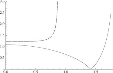
The flutter boundary is sensitive to the dimensionless parameters. In Fig. 5.15, for example, we see a dramatic change in the flutter speed versus the frequency ratio a = mh /шв for a case with very small mass ratio. Even so, the significant drop in the flutter speed for xe = 0.2 around a = 1.4 is of utmost practical importance. There are certain frequency ratios at which the flutter speed becomes very small, depending on the values of the other parameters. This dip is observed in the plot of flutter speed versus frequency ratio for the wings of most high-performance aircraft, which have relatively large mass ratios and positive static unbalances. The chordwise offsets also have a strong influence on the flutter speed, as shown in Fig. 5.16. Indeed, a small change in the mass-center location can lead to a large increase in the flutter speed. The mass-center location, e, cannot be changed without simultaneously changing the dimensionless radius of gyration, r ; however, the relative change in the flutter speed for a small percentage change in the former is more than for a similar percentage change in the latter. These facts led to a concept of mass-balancing wings to alleviate flutter, similar to the way that control surfaces are mass-balanced. If the center of mass is moved forward of the reference point, the flutter speed is generally
|
uf b IPg
Figure 5.15. Plot of dimensionless flutter speed versus frequency ratio for the case n = 3, r = 1/2, and a = —1/5, where the solid line is for xe = 0.2 and the dashed line is for xe = 0.1 |
 |
e
relatively high. Unfortunately, this is not easily accomplished; however, a large change is not usually needed to ensure safety. Note that care must be exercised in examining changes in other parameters caused by such changes in the mass distribution. For example, the torsional frequency may be altered significantly in the process of changing the radius of gyration. Finally, we note that the flutter frequency for bending-torsion flutter is somewhere between and шв, where normally a < 1; however, situations arise in which the flutter frequency may exceed шв.
It is important to note that there are some combinations of the chordwise offset parameters e and a for which the current simplified theories indicate that flutter is not possible. The classic textbook by Bisplinghoff, Ashley, and Halfman (1955) classified the effects of the chordwise offsets e and a in terms of small and large a. For small a, they noted that flutter can happen only when the mass center is behind the quarter-chord (i. e., when e > -1/2); thus, it cannot happen when e < -1/2. For large a, flutter can happen only when the elastic axis is in front of the quarter-chord (i. e., when a < -1/2); thus, it cannot happen when a > -1/2. Moreover, for the typical – section model in combination with the aerodynamic models presented herein, flutter does not appear to happen for any combination of a and r when the mass centroid, elastic axis, and aerodynamic center all coincide (i. e., when e = a = -1/2). Even if this prediction of the analysis is correct, practically speaking, it is difficult to achieve coincidence of these points in wing design. Remember, however, that all of these statements are made with respect to simplified models. We need to analyze real wings in a design setting using powerful tools, such as NASTRAN™ or ASTROS™. Indeed, bending-torsion flutter is a complicated phenomenon and it seems to defy all of our attempts at generalization. Additional discussion of these phenomena, along with a large body of solution plots, is found in Bisplinghoff, Ashley, and Halfman (1955).
The final flutter boundary can be presented in numerous ways for any given flight vehicle. The manner in which it is illustrated depends on the engineering purpose that it is intended to serve. One possible presentation of the flutter boundary is to
|
|
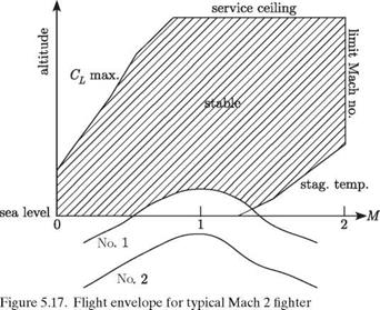
superpose it on the vehicle’s flight envelope. A typical flight envelope for a Mach 2 attack aircraft is illustrated in Fig. 5.17 with two flutter boundaries indicated by the curves marked No. 1 and No. 2. The shaded region above the flutter boundaries, being at higher altitudes, corresponds to stable flight conditions; below the boundaries, flutter will be experienced. Flutter boundary No. 1 indicates that for a portion of the intended flight envelope, the vehicle will experience flutter. Note that these conditions of instability correspond to a flight Mach number near unity (i. e., transonic flow) and high dynamic pressure. This observation can be generalized by stating that a flight vehicle is more susceptible to aeroelastic flutter for conditions of (1) lower altitude, (2) transonic flow, and (3) higher dynamic pressure.
If it is determined that the vehicle will experience flutter in any portion of its intended flight envelope, it is necessary to make appropriate design changes to eliminate the instability for such conditions. These changes may involve alteration of the inertial, elastic, or aerodynamic properties of the configuration; often, small variations in all three provide the best compromise. Flutter boundary No. 2 is indicative of a flutter-safe vehicle. Note that at the minimum altitude-transonic condition, there appears to be a safety margin with respect to flutter instability. All flight-vehicle specifications require such a safety factor, which is generally called the “flutter margin.” Most specifications require that the margin be 15% over the limit-equivalent airspeed. In other words, the minimum flutter speed at sea level should not be less that 1.15 times the airspeed for the maximum expected dynamic pressure as evaluated at sea level.


