Forward Flight Performance of the Autogiro
The performance of the autogiro in forward flight can be approached using the same basic principles of analysis (momentum and blade element theories) that were applied to the helicopter rotor in Chapters 2 and 3. Historically, the methods of helicopter analysis were mostly derived from the actuator disk analysis conducted on the autogiro by Glauert, Lock, Bennett, and Wheatley. There are two basic methods of approach: 1. An analysis based on energy principles (i. e., a net power analysis); and 2. A force and torque balance analysis on the rotor. In each case the principles of the momentum theory introduced in Chapter 2 for the analysis of the helicopter can be used as a basis.
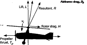
Consider the autogiro in forward flight, as shown in Fig. 12.9. Vertical force equilibrium gives
![]()
 |
||
L = W — T cos a,
▼ Weight, W
Figure 12.9 Forces acting on an autogiro in level flight.
and horizontal equilibrium gives
D = Я cos a + Dp = Tp. (12.13)
Using energy principles the net drag on the autogiro can be written simply as D = P / V^. We know from Chapter 3 that the power can be written as the sum of the profile and induced power required for the rotor, Pq + Р,-, and the power required to overcome airframe drag, Pp. While the rotor of an autogiro is unpowered at the shaft, energy is still required to turn the rotor and overcome induced and profile losses. This source of energy is the relative flow upward through the rotor, which is produced by propelling the aircraft forward with the engine and propeller. Therefore, the power required can be written as
P = P0 + Pi + Pp, (12.14)
as for the helicopter case. These power components are conveniently written in their nondi – mensional form as
![]()
 |
 |
Cp — CpQ + Cpj + Cpp, where each component can be determined as
Cp. = l (t) Д3- (12-18)
z л/
The induced inflow through the rotor is given by the usual result from Chapter 2 that
![]() кСр
кСр
2 yj Д2 + kf
with the usual limits of validity in mind (Section 2.14.5). The induced power factor for the autorotating rotor is typically slightly larger than for the powered rotor in the normal working state (as shown by the results in Fig. 5.30), but it is sufficient to assume that к = 1.2 on average for autogiro performance calculations. Notice that the profile contribution to the power (or drag) must model the performance of the rotor at higher values of д because of the typically lower rpm of the autorotating rotor. Finally, the propulsive force on the autogiro, Tp is produced by a propeller with aerodynamic efficiency rjp. Therefore, the net shaft power required for the autogiro, Pshp is
There are several provisions on the use of the result in Eq. 12.20. First, it will not be applicable at very low airspeeds because it is apparent that P/V^ (or Cp/fi) will become singular. However, the autogiro cannot sustain level flight here anyway because there is a maximum resultant force coefficient that can be sustained on an autorotating rotor (i. e., Cp ~ 1.25). Under the conditions where level flight cannot be sustained, the autogiro will begin to descend and potential energy (altitude) is given up. Second, because of its lower tip speed the rotor operates at high д, so that the applicability of the approximation used for the rotor drag with reverse flow (Eq. 12.16) must be examined. Third, the theory cannot apply
when the disk AoA is large, although from Fig. 12.3 it is clear that this also only occurs at lower speeds and steep angles of descent. Therefore, Eq. 12.20 will apply over most practical level-flight airspeeds. However, it will be apparent that this first form of analysis gives no information about the rotor disk AoA required to actually produce autorotation.
An alternative form of analysis based on a force balance must consider the flow conditions required to produce autorotation (i. e., the AoA of the rotor to produce autorotation at a given airspeed must now be determined). The principles of this following approach was used by – Bennett (1933) and also by Glauert (1935) for his “lifting windmill” problem. To produce autorotation there must be a component of flow upward through the disk (i. e., a component Voo sin a). Because the rotor produces thrust it also creates an induced velocity vt. The net flow upward through the rotor will thus be Voo sin a — u,-, where a is not known a priori. Autorotational conditions will be obtained when the AoA and upward flow is sufficient to overcome both the induced and rotational torque losses of the rotor so that the net shaft torque required will be zero. These losses can be written as
Cq = Cq0 + Cq, = Cq0 + kXCt = 0 for autorotation, (12.21)
where Cq0 is the rotational component of profile torque on the rotor (see Section 5.4.2), which is given by
СЄо = ^(і+М2) (12.22)
and where the inflow ratio (see Section 2.14.1) is given by
Ct
X = ц, tan(—a) -1—- 7:-:_…. . …. (12.23)
2-У /z2 + X2
Notice that a negative sign preceding the a must be used here because the disk is now tilted back compared to the helicopter case. Thus we have
which can be solved numerically for the value of a required to produce autorotation; that is, the value of a required at any д to produce zero net torque (power) required at the rotor shaft. Notice that because vertical force equilibrium must be simultaneously satisfied using Eq. 12.12, the rotor thrust must also increase as a increases because the airspeed decreases (i. e., because CT ^ CV/ cos a). This will apply down to the lower limit of Cr ы 1.25. Having solved for a to produce autorotation, the drag on the autogiro will be
D — T sin a + H cos a – f Dp = Tp, (12.25)
where the rotor drag force coefficient is aC^ Л 1 -Л
CH = -^2n+-^J (12.26)
when including reverse flow but not radial drag – see Section 5.4.2. The shaft power required for flight is then found using
Fshp = TpVoo/r/p, (12.27)
as before. The results from both the energy and force methods are equivalent, although the latter approach has the advantage of being able to solve for the rotor disk AoA required to produce autorotation.
|
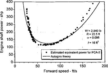
Figure 12.10 Predictions of power required for flight for an autogiro are in good agreement with the momentum theory approach. |
A representative curve of power required versus airspeed for the PCA-2 autogiro is shown in Fig. 12.10. While direct power measurements are not available, it is possible to derive the equivalent shaft pow’er at the engine by using the L/D results in Fig. 12.14 along with an assumed propeller efficiency. It is apparent that this type of performance analysis is in agreement with the measurements. Notice in this case, however, that, compared to a typical helicopter curve, the power requirements for an autogiro increase rapidly as airspeed bleeds off. The performance of the autogiro at these conditions is limited by either the power available or the maximum rotor lift coefficient (see Fig. 12.7). Furthermore, notice that the power requirements increase rapidly at higher airspeeds, which is a result of the high parasitic drag (large equivalent flat plate areas) of the early autogiros.
This theory can also be used to predict the gliding (power-off) rate of descent of the autogiro. The results have been shown previously in Fig. 12.2. Based on an energy balance and solving for the rate of descent, it is apparent that the theory is in excellent agreement with the measured performance of the PCA-2 and C-30 Autogiros, but only at higher forward flight speeds. This is because of the failure of the momentum theory to predict the induced velocity through the rotor at high disk angles of attack (low airspeeds, higher rates of descent). As also shown in Fig. 12.2, Harris’s approximate theory for these conditions seems to fill in nicely where the momentum theory fails.


