Frise Ailerons
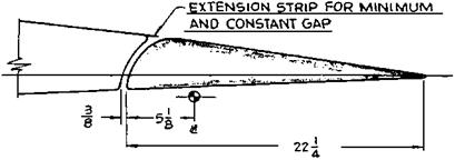
The hinge line of the Frise aileron, invented by Leslie George Frise, is always at or below the wing’s lower surface. If one sees aileron hinge brackets below the wing, chances are that one is looking at a Frise aileron (Figure 5.5). Frise ailerons were used on many historic airplanes after the first World War, including the Boeing XB-15 and B-17, the Bell P-39, the Grumman F6F-3 and TBF, and the famous World War II opponents – the Spitfire, Hurricane, and Focke-Wulf 190 fighters. Frise ailerons were applied to both the Curtiss-Wright C-46 Commando and the Douglas C-54 Skymaster during World War II, to replace the hydraulic boost systems used in their respective prototypes.
With the hinge point below the wing surface, an arc drawn from the hinge point to be tangent to the wing upper surface penetrates the wing lower surface some distance ahead of the hinge line, thus establishing an overhang balance. The gap between the aileron and wing can be made as narrow as desired by describing another arc slightly larger than the first. This in fact is typical of the Frise aileron design. The narrow wing-to-aileron gap reduces air flow from the high-pressure wing under surface to the lower pressure wing upper surface, reducing drag. The Frise aileron is less prone to accumulate ice for that same reason. It was promoted by the U. S. Army Air Corps Handbookfor Airplane Designers asan anti-icing aileron.
The relatively sharp Frise aileron nose develops high velocities and low static pressures when projecting below the wing lower surface, when the aileron goes trailing-edge up. This generally overbalances the up-going aileron. On the other hand, the overbalanced up aileron is connected by control cables or pushrods to the down-going aileron on the other side of the wing. The sharp Frise nose on that side is within the wing contour; the down aileron is underbalanced. By connecting the up and down sides through the pilot’s controls the combination is made stable, with lowered control forces relative to ailerons without aerodynamic balance.
The sharp nose of the Frise aileron, protruding below the wing’s lower surface for trailing – edge-up deflections, has been thought to help reduce adverse yaw when rolling. The trailing – edge-up aileron is on the down-going wing in a roll. In adverse yaw, the down-going wing moves forward, while the airplane yaws in a direction opposite to that corresponding to a
|
Figure 5.5 A Frise aileron design used on the Douglas SBD-1 Dauntless. This design was the seventh and final configuration tested in 1939 and 1940. Nose shape, wing-to-aileron gap, hinge line position, and gap seal parameters were all varied. (From Root, NACA W-81, 1942) |
|
|
|
Figure 5.6 Flight test evidence of Frise aileron oscillations on a Waco XCG-3 glider due to alternate stalling and unstalling of the sharp nose at extreme up-aileron travels. The upper photo shows the bulky roll rate recorder. The lower photo is a rate of roll trace for two abrupt full aileron rolls. Aileron oscillations are shown by the ripples at the peak roll rate values. (From U. S. Army Air Corps photo 89368, 1942) |
coordinated turn. Flow separation from the Frise aileron sharp nose is supposed to increase drag on the down-going wing, pulling it back and reducing adverse yaw. This happens to some extent, but for normal wing plan forms with aspect ratios above about 6, adverse yaw is actually dominated by the aerodynamic yawing moment due to rolling, the derivative Cnp, and is little affected by Frise ailerons. Adverse yaw must be overcome by good directional stability complemented by rudder deflection in harmony with aileron deflection.
Frise ailerons turned out to have problems on large airplanes, where there is a long cable run from the control yoke to the ailerons. In the development of the Waco XCG-3 glider in
1942, the sharp nose of its Frise ailerons alternately stalled and unstalled when the ailerons were held in a deflected position. This created severe buffeting. The aileron nose stalled at the largest angle, reducing the balancing hinge moment. Control cable stretch allowed the aileron to start back toward neutral. But as the aileron angle reduced the nose unstalled, the aerodynamic balance returned, and the aileron started back toward full deflection, completing the cycle (Figure 5.6).
The fix for the XCG-3 was to limit up-aileron angles from 30 to 20 degrees and to round off the sharp nose to delay stalling of the nose. Modified Frise ailerons, with noses raised to delay stalling, had been tested in Britain by A. S. Hartshorn and F. B. Bradfield as early as 1934. The advantages of raised-nose Frise ailerons were verified in NACA tests on a Curtiss P-40 (Goranson, 1945). Beveled trailing edges were added to the raised-nose Frise ailerons on the P-40, to make up for loss in aerodynamic balance at small deflections. Lateral stick force remained fairly linear and very low up to a total (sum of up and down) aileron deflection of 48 degrees, giving a remarkably high dimensionless roll rate pb/2V of 0.138 at 200 miles per hour.


