General Lift Distribution
Consider the transformation
у — —— cos в [5.46]
2
where the coordinate in the spanwise direction is now given by в, with 0 < в < л. In terms of в, the elliptic lift distribution given by Equation (5.31) is written as
Г(0) = Г0 sin0 [5.47]
Equation (5.47) hints that a Fourier sine series would be an appropriate expression for the general circulation distribution along an arbitrary finite wing. Hence, assume for the general case that
N
Г(0) = 2bV, A„ sin пв [5.48]
l
where as many terms N in the series can be taken as we desire for accuracy. The coefficients An (where n = 1,…, N) in Equation (5.48) are unknowns; however, they must satisfy the fundamental equation of Prandtl’s lifting-line theory; that is, the An’s must satisfy Equation (5.23). Differentiating Equation (5.48), we obtain
![]()
|
|
|||
|
||||
![]() Substituting Equations (5.48) and (5.49) into (5.23), we obtain
Substituting Equations (5.48) and (5.49) into (5.23), we obtain
2b ■Дл 1 fn y’f «A„ cos «0 , ,
а (во) = —V A„ sin «ft, + аь=о(во) + ————- ^— — dQ [5.50]
7Tc(0o) , 7T Jq cos в — COS Oq
 |
||
The integral in Equation (5.50) is the standard form given by Equation (4.26). Hence, Equation (5.50) becomes
Examine Equation (5.51) closely. It is evaluated at a given spanwise location; hence, во is specified. In turn, b, с(во), and а/=о(во) are known quantities from the geometry and airfoil section of the finite wing. The only unknowns in Equation (5.51) are the A„’s. Hence, written at a given spanwise location (a specified во), Equation (5.51) is one algebraic equation with N unknowns, Ab A2,…, A„. However, let us choose N different spanwise stations, and let us evaluate Equation (5.51) at each of these N stations. We then obtain a system of N independent algebraic equations with N unknowns, namely, А,, Аг,…, A, y. In this fashion, actual numerical values are obtained for the A„’s—numerical values that ensure that the general circulation distribution given by Equation (5.48) satisfies the fundamental equation of finite-wing theory, Equation (5.23).
|
2 Ch/2 2h[16] Cl = 77—- / Г(y)dy = —J2A4 si J-b/2 J , JO |
 |
||
Now that Г(0) is known via Equation (5.48), the lift coefficient for the finite wing follows immediately from the substitution of Equation (5.48) into (5.26):
Hence, Equation (5.52) becomes
![]() CL = Аіяу = Ai7tAR
CL = Аіяу = Ai7tAR
Note that Cl depends only on the leading coefficient of the Fourier series expansion. (However, although Cl depends on A i only, we must solve for all the A„’s simultaneously in order to obtain A.)
The induced drag coefficient is obtained from the substitution of Equation (5.48) into Equation (5.30) as follows:
![]()
|
|
|
|

 |
|
The induced angle of attack a, (в) in Equation (5.54) is obtained from the substitution of Equations (5.46) and (5.49) into (5.18), which yields
The integral in Equation (5.55) is the standard form given by Equation (4.26). Hence, Equation (5.55) becomes
|
E |
sin nSo
nA„ ——— [5.56]
, Sin во
In Equation (5.56), 60 is simply a dummy variable which ranges from 0 to ж across the span of the wing; it can therefore be replaced by в, and Equation (5.56) can be written as
|
E |
![]()
![]() sin пв пА„ —
sin пв пА„ —
С1Г
1
 |
|
Substituting Equation (5.57) into (5.54), we have
Examine Equation (5.58) closely; it involves the product of two summations. Also, note that, from the standard integral,
Hence, in Equation (5.58), the mixed product terms involving unequal subscripts (such as A1A2, A2A4) are, from Equation (5.59), equal to zero. Hence, Equation
(5.58) becomes
9,2 / N V
cD, i – (J2 nAln) у = лARZ! иЛ»
Substituting Equation (5.53) for Cl into Equation (5.60), we obtain
![]()
|
|||
|
|
||
where S = Y^2 n{An/A] )2. Note that S > 0; hence, the factor 1 + S in Equation
(5.61)
is either greater than 1 or at least equal to 1. Let us define a span efficiency factor, e, as e = (1 + <5)_1. Then Equation (5.61) can be written as
where e < 1. Comparing Equations (5.61) and (5.62) for the general lift distribution with Equation (5.43) for the elliptical lift distribution, note that 5 = 0 and e = 1 for the elliptical lift distribution. Hence, the lift distribution which yields minimum induced drag is the elliptical lift distribution. This is why we have a practical interest in the elliptical lift distribution.
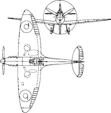
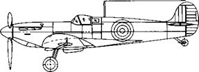
Recall that for a wing with no aerodynamic twist and no geometric twist, an elliptical lift distribution is generated by a wing with an elliptical planform, as sketched at the top of Figure 5.16. Several aircraft have been designed in the past with elliptical wings; the most famous, perhaps, being the British Spitfire from World War II, shown in Figure 5.17. However, elliptic planforms are more expensive to manufacture than, say, a simple rectangular wing as sketched in the middle of Figure 5.16. On the other hand, a rectangular wing generates a lift distribution far from optimum. A compromise is the tapered wing shown at the bottom of Figure 5.16. The tapered wing can be designed with a taper ratio, that is, tip chord/root chord ее ct/cr, such that the lift distribution closely approximates the elliptic case. The variation of S as a function of taper ratio for wings of different aspect ratio is illustrated in Figure 5.18. Such calculations of S were first performed by the famous English aerodynamicist, Hermann Glauert and published in Reference 18 in the year 1926. Note from Figure 5.18 that a tapered wing can be designed with an induced drag coefficient reasonably close to the minimum value. In addition, tapered wings with straight leading and trailing
Elliptic wing
|
|
|
|
Figure 5.1 7 Three views of the Supermarine Spitfire, a famous British World War II fighter. |
edges are considerably easier to manufacture than elliptic planforms. Therefore, most conventional aircraft employ tapered rather than elliptical wing planforms.


