General Three-Dimensional Flows: Panel Techniques
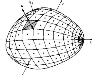
In modem aerodynamic applications, three-dimensional, inviscid, incompressible flows are almost always calculated by means of numerical panel techniques. The philosophy of the two-dimensional panel methods discussed in previous chapters is readily extended to three dimensions. The details are beyond the scope of this book—indeed, there are dozens of different variations, and the resulting computer programs are frequently long and sophisticated. However, the general idea behind all such panel programs is to cover the three-dimensional body with panels over which there is an unknown distribution of singularities (such as point sources, doublets, or vortices). Such paneling is illustrated in Figure 6.7. These unknowns are solved through a system of simultaneous linear algebraic equations generated by calculating the induced velocity at control points on the panels and applying the flow-tangency
|
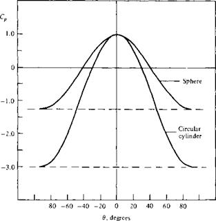
Figure 6.6 The pressure distribution over the surface of a sphere and a cylinder. Illustration of the three-dimensional relieving effect. |
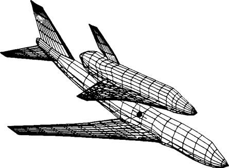
condition. For a nonlifting body such as illustrated in Figure 6.7, a distribution of source panels is sufficient. However, for a lifting body, both source and vortex panels (or their equivalent) are necessary. A striking example of the extent to which panel methods are now used for three-dimensional lifting bodies is shown in Figure 6.8, which illustrates the paneling used for calculations made by the Boeing Company of the potential flow over a Boeing 747-space shuttle piggyback combination. Such applications are very impressive; moreover, they have become an industry standard and are today used routinely as part of the airplane design process by the major aircraft companies.
Examining Figures 6.7 and 6.8, one aspect stands out, namely, the geometric complexity of distributing panels over the three-dimensional bodies. How do you get the computer to “see” the precise shape of the body? How do you distribute the panels over the body; that is, do you put more at the wing leading edges and less on the fuselage, etc.? How many panels do you use? These are all nontrivial questions. It is not unusual for an aerodynamicist to spend weeks or even a few months determining the best geometric distribution of panels over a complex body.
We end this chapter on the following note. From the time they were introduced in the 1960s, panel techniques have revolutionized the calculation of three-dimensional potential flows. However, no matter how complex the application of these methods may be, the techniques are still based on the fundamentals we have discussed in this
|
|
|
Panel distribution for the analysis of the Boeing 747 carrying the space shuttle orbiter. (Courtesy of the Boeing Airplane Company.)
and all the preceding chapters. You are encouraged to pursue these matters further by reading the literature, particularly as it appears in such journals as the Journal of Aircraft and the AIAA Journal.


