Generalized Panel Methods
Following the pioneering vortex lattice work, computational fluid dynamics programs of increasing complexity have been developed, such as PAN AIR by Boeing, QUADPAN at Lockheed, Analytical Methods, Inc.’s, VSAERO, and MCAERO at McDonnell-Douglas. These approaches have included the Neumann problem in potential flow (Smith, 1962), inviscid Euler methods (Jameson, 1981), and full-blown Navier-Stokes equation solutions (Pulliam, 1989).
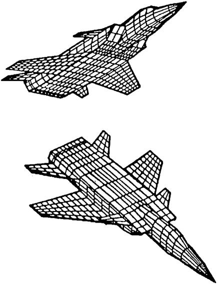
Vortex lattice, Euler, and Navier-Stokes methods are now used to generate airplane stability and control data at the preliminary design stage in much the same way that wind-tunnel models were used in earlier times. The computer defines and stores the three-dimensional panel geometry approximating the airframe shape, as in Figure 6.4. Aircraft lift curve slopes, static longitudinal and lateral stability, control effectiveness, and even rotary derivatives are well predicted for small angles of attack, sideslip, and control deflection.
6.1 Estimation from Wind-Tunnel Data
Manufacturers of transport and military airplanes spend a great deal of money and engineering effort on wind-tunnel testing in developing new designs. These costs are rarely questioned anymore; one just budgets wind-tunnel testing at a generous level. Yet, how well can one expect wind-tunnel test results to match stability and control flight test results? This question was dealt with in an early NACA study (Kayten and Koven, 1945). Both engineers later led the stability and control branch in the U. S. Naval Air Systems Command.
Kayten and Koven compared wind-tunnel and flight test measurements for the Douglas A-26 Invader twin-engine attack airplane. The discrepancies were larger than one might have expected. Most of the discrepancies could be explained after the fact, but one is left with the uneasy feeling that wind-tunnel tests can give engineers a distinctly cloudy crystal ball. The factors that led to discrepancies in the case of the A-26 were
1. The geometric wing dihedral was greater in flight than in the wind tunnel due to upward bending under load. This problem could be dealt with by giving tunnel models extra wing dihedral based on calculated bending deflections.
|
Figure 6.4 PAN AIR panel geometry for a computational fluid dynamic analysis of a complete airplane configuration. (From Tinico, Boeing Commercial Airplane Group, 1992) |
2. Control surface contours in flight differed from the wind-tunnel model because of fabric distortion. Thisproblem mayhave effectivelyvanished, since fabric-covered control surfaces are now rarely used.
3. There was premature inboard wing stalling in flight that was not present on the smooth, well-faired wind-tunnel model wing. This last problem is of the type that is difficult to deal with in advance. However, the current approach might be to clean up the airplane’s premature wing stalling by refairing or vortex generators, incidentally bringing about better agreement between the wind-tunnel and flight data.
In spite of discrepancies such as these, designers ignore unfavorable wind-tunnel results at their peril. For example, before it was flown, power model tests of the Martin 202 showed that its one-piece wing would have negative effective dihedral in the power approach condition. The results were dismissed with the comment, “It’s only a wind – tunnel test,” but an expensive redesign was needed later.
CHAPTER 7


