Helicopter Equilibrium in the Hovering Regime
The conditions of helicopter equilibrium in the hovering regime can be applied (with some additions) to any flight regime.
Hub horizontal hinge offset. Most modern helicopters have offset of the main rotor hub horizontal hinges, i. e., separation between the hub axis and the horizontal hinge axis, which is denoted by (Figure 95a). Horizontal
hinge offset has an effect on helicopter equilibrium, stability, and controllability conditions.
The centrifugal forces acting on the rotor blades are transmitted to the horizontal hinges. When the main rotor plane of rotation is parallel to the hub plane (no tilt of the coning axis), the blade centrifugal forces are in

a single plane and their moment relative to the center of the hub equals zero.
If the main rotor coning axis is deflected from the hub axis, the main rotor plane of rotation will not be parallel to the hub rotation plane. The blade centrifugal forces act in a plane parallel to the main rotor plane (Figure 95b).
![]() If the horizontal hinges are offset, there will be an arm c between the centrifugal forces; therefore, these forces create the moment = Nc relative to the center of the hub. This moment rotates the main rotor hub and consequently the entire helicopter so as to make the hub axis approach the coning axis.
If the horizontal hinges are offset, there will be an arm c between the centrifugal forces; therefore, these forces create the moment = Nc relative to the center of the hub. This moment rotates the main rotor hub and consequently the entire helicopter so as to make the hub axis approach the coning axis.
Equilibrium of the helicopter relative to the principal axes of rotation can be subdivided into longitudinal, transverse, and directional. Common to all these modes is the first equilibrium characteristic: uniform rectilinear
motion or, as a particular case, relative rest in the hovering regime (V = 0). Therefore, in the definitions of the equilibrium modes we omit the first characteristic, assuming that it holds.
Helicopter longitudinal equilibrium is that state of the helicopter in which it does not rotate about the transverse axis. Since the velocity in the hovering regime equals zero, there will be no forces parallel to the helicopter longitudinal axis. Then the first equilibrium characteristic is
expressed by the two equalities
The second equilibrium condition is that the sum of the longitudinal moments must equal zero: EM^ = 0.
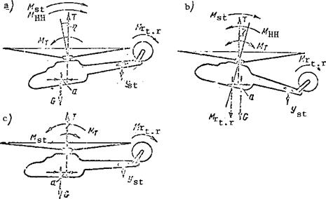
Longitudinal moments are created by (Figure 96):
main rotor thrust force (M^ = Та);
stabilizer lift force (M. = Y L.);
st st st
horizontal hinge moment (M^ = NC);
tail rotor reactive moment де.
r
t. r
![]()
If the eg location is far forward the helicopter will hover with the nose down (Figure 96a). In this case the main rotor thrust force moment will be nose-down; the moments of the horizontal hinges, stabilizer, and the tail rotor reactive moment are nose-up. Therefore, the second longitudinal °quilibrium characteristic is expressed by the equation
or
NC + Y. L. 4 M – Та = 0. st st r
t. r
To satisfy this condition the main rotor coning axis must be tilted aft. The more forward the eg, the larger the coning axis deflection angle л must be.
If the eg moves forward beyond the limiting forward position, hovering longitudinal equilibrium cannot be achieved.
|
Figure 96. Helicopter longitudinal equilibrium in hover. |
If the helicopter eg is aft or slightly forward, the helicopter will hover with the nose high (Figure 96b). In this case the main rotor coning axis must be deflected forward relative to the hub axis through the angle n. The moment of the main rotor thrust force may be positive, negative, or zero. The moment of the stabilizer and tail rotor, as in the first case, will be nose-up. The second equilibrium characteristic will be expressed by the equality
Mst+Mr ±“1-^ = °.
t. r
If the helicopter eg moves aft beyond the permissible limit, the main rotor coning axis is deflected full forward. In this case the helicopter cannot be transitioned into the horizontal flight regime, and if this cannot be done the flight speed cannot be increased to the maximal value.
Helicopter hover in the horizontal attitude is possible with a slightly forward eg location. In this case the main rotor coning axis will coincide
with the hub axis. The moment of the horizontal hinges will be zero. The main rotor thrust force will be nose-down (Figure 96c). The longitudinal equilibrium condition is expressed by the equality
Longitudinal equilibrium of the helicopter in other flight regimes as a function of eg location can be expressed by one of the equalities discussed above. However, to the terms of these equalities we must also add the helicopter parasite drag force moment, which will generally be a climbing moment.
Helicopter transverse equilibrium is that state of the helicopter in which there is no rotation about the longitudinal axis. The transverse equilibrium conditions are expressed in general form by the following equalities: = 0, no side displacement, this equality expresses the first
![]() transverse equilibrium characteristic; £Mx = 0, no rotation about the longitudinal axis, this equality expresses the second transverse equilibrium characteristic.
transverse equilibrium characteristic; £Mx = 0, no rotation about the longitudinal axis, this equality expresses the second transverse equilibrium characteristic.
In order to express the transverse equilibrium conditions through the forces acting on the helicopter during hovering and through the transverse moments of these forces, we must examine the conditions for equilibrium of the single-rotor helicopter without an aft fin and the single-rotor helicopter with an aft fin.
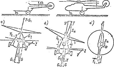
In the single-rotor helicopter without an aft fin, the tail rotor is located right on the tail boom (Figure 97a).
This helicopter can have transverse equilibrium in the hover regime only in the presence of a bank in the direction opposite the tail rotor thrust (Figure 97c). A side component of the weight force = G sin у (у is the
|
Figure 97. Helicopter lateral equilibrium. |
bank angle) is formed when the helicopter banks. This component balances the tail rotor thrust force. Then the equality expressing the first transverse equilibrium characteristic is written as follows
T = G = G sin у or T – G„ = 0 . t. r 2 ‘ t. r 2 •
Hence we find the magnitude of the bank angle
T_
. t. r
у = arcsm—–
G
The thrust force vector is not deflected from the helicopter symmetry
plane, therefore the thrust force moment about the helicopter longitudinal
axis will be zero. The moment of the horizontal hinges will also be zero.
The tail rotor thrust force is applied to the longitudinal axis of the
helicopter, and its moment will also be zero. Therefore, the second helicopter
equilibrium characteristic will be expressed in general form by the equality
EM = 0. x
The transverse equilibrium of this type of helicopter in the other flight regimes can be achieved in the same way as in the hover regime, i. e., by banking; or it can be obtained by sideslipping the helicopter in the direction of the tail rotor thrust (Figure 97d)• During the sideslip there is formed the side air pressure force on the fuselage, and this force balances the tail rotor thrust force
The advantages of the helicopter of this type are: lower loading on
the tail boom, since there is no twisting moment of the tail rotor thrust force, and lower helicopter weight in view of absence of the vertical fin.
The disadvantages of the helicopter include:
(1) large bank angle during hover, which creates discomfort for passengers and crew and makes helicopter control difficult;
(2) large bank angle or large sideslip in translational flight, which increases helicopter parasite drag;
(3) probability of damage to the tail rotor in view of its very low position;
(4) danger to servicing personnel because of the low tail rotor location.
Therefore, helicopters without a vertical fin are seldom encountered.
The presence of a vertical fin on which the tail rotor is mounted eliminates these drawbacks, since the tail rotor is raised above the ground and its axis approaches the main rotor plane of rotation (Figure 97b). Let us examine the transverse equilibrium of a helicopter with vertical fin (Figure 97d). This helicopter, like the helicopter without a vertical fin, hovers with a bank angle, but the bank angle will be small, about 1°, and is not noticeable
in practice. The necessity for the bank angle follows from the transverse equilibrium conditions. The bank angle leads to the side component G^ – G sin у of the weight force. The first transverse equilibrium criterion will be expressed by the equatior
![]()
![]()
S + G_ or T
S 2 t.
(S= + G_) = 0. s 2
|
|
|
|
|
|
|
|
|
|
|
|
 |
|
|
|
|
|
![]()
But T = S ; therefore contradictory requirements are obtained: the
t • IT s
tail rotor thrust must at the same time be larger than and equal to the side force, which is not possible; therefore a small bank angle and the side weight force G2 are required for equilibrium.
During flight with translational velocity, transverse equilibrium is achieved either as a result of a bank angle, as in hovering, or as the result of sideslip, which results in side pressure force on the fuselage. The transverse equilibrium condition will be expressed by the equalities
![]()
 Ф
Ф
Heliconter directional equilibrium is the state of the helicopter in which it does not rotate about the vertical axis. The directional equilibrium conditions are
To ensure the latter condition it is necessary that the reactive moment be balanced by the moments of tail rotor thrust and main rotor thrust side force. Then
Here the following circumstance must be noted. With change of the main rotor thrust there will also be a change of its reactive moment, i. e., the directional equilibrium will be disturbed. Therefore, when the main rotor thrust is changed, it is necessary to change the tail rotor thrust to preserve directional equilibrium. But this requirement complicates the control helicopter.
In the translational flight regimes with horizontal velocity, directional /159 equilibrium is achieved in the same way as in the hovering regime
where b is the distance from the point of application of the force Z^ to the helicopter vertical axis.


