Historical Note: Early Airplane Design and the Role of Airfoil Thickness
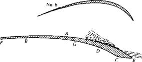
In 1804, the first modem configuration aircraft was conceived and built by Sir George Cayley in England—it was an elementary hand-launched glider, about a meter in length, and with a kitelike shape for a wing as shown in Figure 4.44. (For the pivotal role played by George Cayley in the development of the airplane, see the extensive historical discussion in chapter 1 of Reference 2.) Note that right from the beginning of the modem configuration aircraft, the wing sections were very thin— whatever thickness was present, it was strictly for structural stiffness of the wing. Extremely thin airfoil sections were perpetuated by the work of Horatio Phillips in England. Phillips carried out the first serious wind-tunnel experiments in which the aerodynamic characteristics of a number of different airfoil shapes were measured. (See section 5.20 of Reference 2 for a presentation of the historical development of airfoils.) Some of Phillips airfoil sections are shown in Figure 4.45—note that they are the epitome of exceptionally thin airfoils. The early pioneers of aviation such as Otto Lilienthal in Germany and Samuel Pierpont Langley in America (see
|
|
|
|
|
|
|
|
|
|
|
|
|
![]()
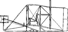
chapter 1 of Reference 2) continued this thin airfoil tradition. This was especially true of the Wright brothers, who in the period of 1901-1902 tested hundreds of different wing sections and planform shapes in their wind tunnel in Dayton, Ohio (recall our discussion in Section 1.1 and the models shown in Figure 1.2). A sketch of some of the Wrights’ airfoil sections is given in Figure 4.46—for the most part, very thin sections. Indeed, such a thin airfoil section was used on the 1903 Wright Flyer, as can be readily seen in the side view of the Flyer shown in Figure 4.47. The important point here is that all of the early pioneering aircraft, and especially the Wright Flyer, incorporated very thin airfoil sections—airfoil sections that performed essentially like the flat plate results discussed in Section 4.12, and as shown in Figure 4.36 (the dashed curve) and by the streamline pictures in Figure 4.37. Conclusion: These early airfoil sections suffered flow-field separation at small angles of attack and, consequently, had low values of c; max. By the standards we apply today, these were simply very poor airfoil sections for the production of high lift.
-VZV77777,
|
|
|
Figure 4.46 Some typical airfoil shapes tested by the Wright brothers in their wind tunnel during 1902-1903.
|
|
Figure 4.47 Front and side views of the 1903 Wright Flyer. Note the thin airfoil sections. ICourtesy of the National Air and Space Museum.) |
This situation carried into the early part of World War I. In Figure 4.48, we see four airfoil sections that were employed on World War I aircraft. The top three sections had thickness ratios of about 4 to 5 percent and are representative of the type of sections used on all aircraft until 1917. For example, the SPAD XIII (shown in Figure 3.50),
|
|
|
|
|
|
|
|

![]()

the fastest of all World War I fighters, had a thin airfoil section like the Eiffel section shown in Figure 4.48. Why were such thin airfoil sections considered to be the best by most designers of World War I aircraft? The historical tradition described above might be part of the answer—a tradition that started with Cayley. Also, there was quite clearly a mistaken notion at that time that thick airfoils would produce high drag. Of course, today we know the opposite to be true; review our discussion of streamlined shapes in Section 1.11 for this fact. Laurence Loftin in Reference 48 surmises that the mistaken notion might have been fostered by early wind-tunnel tests. By the nature of the early wind tunnels in use—small sizes and very low speeds—the data were obtained at very low Reynolds numbers, less than 100,000 based on the airfoil-chord length. These Reynolds numbers are to be compared with typical values in the millions for actual airplane flight. Modem studies of low Reynolds number flows over conventional thick airfoils (e. g., see Reference 51) clearly show high-drag coefficients, in contrast to the lower values that occur for the high Reynolds number associated with the flight of full-scale aircraft. Also, the reason for the World War I airplane designer’s preference for thin airfoils might be as simple as the tendency to follow the example of the wings of birds, which are quite thin. In any event, the design of all English, French, and American World War I aircraft incorporated thin airfoils and, consequently, suffered from poor high-lift performance. The fundamentals of airfoil aerodynamics as we know them today (and as being presented in this book) were simply not sufficiently understood by the designers during World War I. In turn, they never appreciated what they were losing.
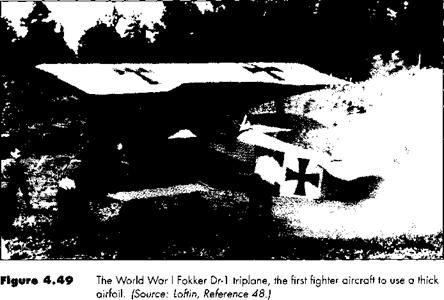
This situation changed dramatically in 1917. Work carried out in Germany at the famous Gottingen aerodynamic laboratory of Ludwig Prandtl (see Section 5.8 for a biographical sketch of Prandtl) demonstrated the superiority of a thick airfoil section, such as the Gottingen 298 section shown at the bottom of Figure 4.48. This revolutionary development was immediately picked up by the famous designer Anthony Fokker, who incorporated the 13-percent-thick Gottingen 298 profile in his new Fokker Dr-1—the famous triplane flown by the “Red Baron,” Rittmeister Manfred Freiher von Richthofen. A photograph of the Fokker Dr-1 is shown in Figure 4.49. The major benefits derived from Fokker’s use of the thick airfoil were:
1. The wing structure could be completely internal; that is the wings of the Dr – 1 were a cantilever design, which removed the need for the conventional wire bracing that was used in other aircraft. This, in turn, eliminated the high drag associated with these interwing wires, as discussed at the end of Section 1.11. For this reason, the Dr-1 had a zero-lift drag coefficient of 0.032, among the lowest of World War I airplanes. (By comparison the zero-lift drag coefficient of the French SPAD XIII was 0.037.)
2. The thick airfoil provided the Fokker Dr-1 with a high maximum lift coefficient. Its performance was analogous to the upper curves shown in Figure 4.36. This in turn, provided the Dr-1 with an exceptionally high rate-of-climb as well as enhanced maneuverability—characteristics that were dominant in dog-fighting combat.
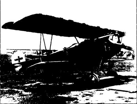
Anthony Fokker continued the use of a thick airfoil in his design of the D-VII, as shown in Figure 4.50. This gave the D-VII a much greater rate-of-climb than its two principal opponents at the end of the war—the English Sopwith Camel and the
|
|
|
Figure 4.50 The World War I Fokker D-VII, one of the most effective fighters of the war, due in part to its superior aerodynamic performance allowed by a thick airfoil section. |
French SPAD XIII, both of which still used very thin airfoil sections. This rate-of – climb performance, as well as its excellent handling characteristics, singled out the Fokker D-VII as the most effective of all German World War I fighters. The respect given by the Allies to this machine is no more clearly indicated than by a paragraph in article IV of the armistice agreement, which lists war material to be handed over to the Allies by Germany. In this article, the Fokker D-VII is specifically listed—the only airplane of any type to be explicitly mentioned in the armistice. To this author’s knowledge, this is the one and only time where a breakthrough in airfoil technology is essentially reflected in any major political document, though somewhat implicitly.


