Momentum Integral Method for Arbitrary Pressure Gradients
A powerful approximate method obtained by applying the momentum theorem to a boundary-layer flow is discussed next. This method of solution does not yield the boundary-layer-velocity profile directly, as did the Blasius and Falkner-Skan solutions. Rather, a velocity-profile function is assumed that contains a dimensionless parameter incorporating an arbitrary pressure gradient. Substituting this assumed profile into the momentum integral produces expressions for 8(x), 8*(x), 0(x), and Cf (x) in the presence of a specified but arbitrary pressure gradient, expressed in the form of the external flow, Ue(x). The resulting velocity profiles are no longer similar because the mathematical requirements that led to that special condition are no longer satisfied. Numerical methods for solving the momentum-integral equation are described after the equation is derived.
Momentum-Integral Equation
The momentum-integral relationship (attributed to von Karman) may be derived by either combining the continuity and momentum-differential equations for the
boundary layer and then integrating across the boundary layer, or applying the momentum theorem to a fixed control volume within the boundary layer. The latter approach is used here because it represents another application of the Conservation of Momentum Principle discussed in Chapter 3. Steady flow is assumed, and the resulting equation is applicable to both laminar and turbulent boundary layers.
Consider a boundary layer growing on a flat plate in the presence of a stream – wise pressure gradient, Ue(x), as illustrated in Fig. 8.24.
A fixed-control volume, у, is chosen that extends from the wall to the edge of the boundary layer and is Ax in length. It is assumed that the boundary-layer approximations hold so that w/u << 1 (i. e., the boundary-layer flow is normal to the vertical sides of у) and dp/dz = 0. Also, the shear stress along the top surface of у is negligible compared to the pressure stress there, and the normal viscous stresses on the vertical sides of у are ignored compared to the pressure stress. Then, from Eq. 3.1, the momentum theorem in the x-direction applied to У may be written as follows:
JJри(v • n)dS – – Up(n • i)d. S + JJ (t. i)dS (8.93)
S S
[1] [2] [3]
Each term is detailed in turn, as follows:
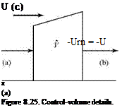
[1] The net-momentum-flux expression consists of the following three terms, as shown in Fig. 8.25a: §
(a) Inflow through the left face, J pu(-u)dz.
0
![]()
![]()
![]() §
§
![]()
 |
Outflow through the right face, J pu(+u)dz
0
(c) Momentum entering the slant upper surface of у, namely, (-Uem).
Recall that the edge of the boundary layer is not a streamline. The mass flux m entering through the upper surface is the difference between the mass flux out through the right face of у and the mass flux in through the left face of V, or:
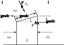
[2] The net pressure force on the control surface consists of the following three terms, as shown in Fig. 8.25b:
(a) The pressure force on the left face, (pS).
(b) ![]()
 |
 |
 |
|
The pressure force on the right face,
(c)
The horizontal component of Fp; namely, FH = Fp sinp = Fp(AS/As), where Fp is evaluated at the midpoint of the interval Ax as:
where the area is (s)(1) because the flow is two-dimensional. Thus,
![]() FH =
FH =
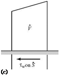
[3] The net shear stress acting on the surface of the control volume is shown in Fig. 8.25c. The shear stress on the upper surface is negligible, whereas the shear stress on the two vertical faces of the control volume is at right angles to the x-direction. The only shear-stress term of interest is the shear force acting on the lower surface of the control volume. The fluid pulls the plate to the right (i. e., drag); hence, the force on the control surface due to the plate is directed to the left. Thus, the shear force is – Tw(x)(1).
Now, we substitute all of these seven terms into Eq. 8.93. Then, we divide through by (Ax) and take the limit as Ax ^ 5x, which, in [2](c) makes AS/Ax ^ dS/dx.
Expanding, simplifying, and neglecting one higher-order term in [2](c) results in the following equation:
This is the Karman momentum integral for steady flow. The student should fill in the details of the derivation of Eq. 8.94. The upper limit in this equation is 5 rather than ^ because an assumed velocity profile can be expressed in terms of z/5 so that at z = 5, u = Ue .
Eq. 8.72 can be written in an equivalent form, as follows:
Collecting and multiplying through by a minus sign, Eq. 8.95 becomes:
|
[pU’20]+Zb [pU’5 *] |
or:
Finally, expanding the first term of Eq. 8.74 by the chain rule and then dividing by
U2e:
where H = 5*/0, the shape factor defined previously. This is the most commonly used form of the Karman momentum integral for steady, incompressible, boundary-layer flow.


