Nonlifting Flows over Arbitrary Bodies: The Numerical Source Panel Method
In this section, we return to the consideration of nonlifting flows. Recall that we have already dealt with the nonlifting flows over a semi-infinite body and a Rankine oval and both the nonlifting and the lifting flows over a circular cylinder. For those cases, we added our elementary flows in certain ways and discovered that the dividing streamlines turned out to fit the shapes of such special bodies. However, this indirect method of starting with a given combination of elementary flows and seeing what body shape comes out of it can hardly be used in a practical sense for bodies of arbitrary shape. For example, consider the airfoil in Figure 3.37. Do we know in advance the correct combination of elementary flows to synthesize the flow over this specified body? The answer is no. Rather, what we want is a direct method; that is, let us specify the shape of an arbitrary body and solve for the distribution of singularities which, in combination with a uniform stream, produce the flow over the given body. The purpose of this section is to present such a direct method, limited for the present to nonlifting flows. We consider a numerical method appropriate for solution on a high-speed digital computer. The technique is called the source panel method, which, since the late 1960s, has become a standard aerodynamic tool in industry and most research laboratories. In fact, the numerical solution of potential flows by both source and vortex panel techniques has revolutionized the analysis of low-speed flows. We return to various numerical panel techniques in Chapters 4 through 6. As a modem student of aerodynamics, it is necessary for you to become familiar with the fundamentals of such panel methods. The purpose of the present section is to introduce the basic ideas of the source panel method, which is a technique for the numerical solution of nonlifting flows over arbitrary bodies.
First, let us extend the concept of a source or sink introduced in Section 3.10. In that section, we dealt with a single line source, as sketched in Figure 3.21. Now imagine that we have an infinite number of such line sources side by side, where the strength of each line source is infinitesimally small. These side-by-side line sources form a source sheet, as shown in perspective in the upper left of Figure 3.38. If we look along the series of line sources (looking along the z axis in Figure 3.38), the source sheet will appear as sketched at the lower right of Figure 3.38. Here, we are looking at an edge view of the sheet; the line sources are all perpendicular to the page. Let s be the distance measured along the source sheet in the edge view. Define X = X(s) to be the source strength per unit length along s. [To keep things in perspective, recall from Section 3.10 that the strength of a single line source Л was defined as the volume flow rate per unit depth, that is, per unit length in the z direction. Typical units for Л are square meters per second or square feet per second. In turn, the strength of a source sheet A.(.v) is the volume flow rate per unit depth (in the z direction) and per unit length (in the s direction). Typical units for X are meters per second or feet per second.] Therefore, the strength of an infinitesimal portion ds
|
|
|
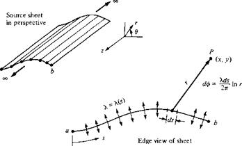
of the sheet, as shown in Figure 3.38, is Xds. This small section of the source sheet can be treated as a distinct source of strength X ds. Now consider point P in the flow, located a distance r from ds the cartesian coordinates of P are (x, у). The small section of the source sheet of strength X ds induces an infinitesimally small potential d<p at point P. From Equation (3.67), d<p is given by
![]() [3.141]
[3.141]
The complete velocity potential at point P, induced by the entire source sheet from a to b, is obtained by integrating Equation (3.141):
Note that, in general, X(s) can change from positive to negative along the sheet; that is, the “source” sheet is really a combination of line sources and line sinks.
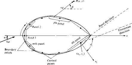
Next, consider a given body of arbitrary shape in a flow with freestream velocity Vqo, as shown in Figure 3.39. Let us cover the surface of the prescribed body with a source sheet, where the strength X(s) varies in such a fashion that the combined action of the uniform flow and the source sheet makes the airfoil surface a streamline of the flow. Our problem now becomes one of finding the appropriate X(s). The solution of this problem is carried out numerically, as follows.
Let us approximate the source sheet by a series of straight panels, as shown in Figure 3.40. Moreover, let the source strength X per unit length be constant over a given panel, but allow it to vary from one panel to the next. That is, if there are a total of n panels, the source panel strengths per unit length are X ], X2,…, Xj…, Xn. These panel strengths are unknown; the main thrust of the panel technique is to solve for Xj, j — 1 to n, such that the body surface becomes a streamline of the flow. This boundary condition is imposed numerically by defining the midpoint of each panel
|
|||
|
|||
|
|
||
|
|||
|
![]()
to be a control point and by determining the kj ’s such that the normal component of the flow velocity is zero at each control point. Let us now quantify this strategy.
Let P be a point located at (x, y) in the flow, and let r[4 be the distance from any point on the / th panel to P, as shown in Figure 3.40. The velocity potential induced at P due to the y’th panel A<f>j is, from Equation (3.142),
Equation (3.146) is physically the contribution of all the panels to the potential at the control point of the ith panel.
Recall that the boundary condition is applied at the control points; that is, the normal component of the flow velocity is zero at the control points. To evaluate this component, first consider the component of freestream velocity perpendicular to the panel. Let n, be the unit vector normal to the ith panel, directed out of the body, as shown in Figure 3.40. Also, note that the slope of the ith panel is (dy/dx)j. In general, the freestream velocity will be at some incidence angle a to the x axis, as shown in Figure 3.40. Therefore, inspection of the geometry of Figure 3.40 reveals that the component of Voo normal to the ith panel is
![]() koo, n — Vco • n, — Voo CDS
koo, n — Vco • n, — Voo CDS
where Pi is the angle between and n, . Note that V7^ ,, is positive when directed away from the body, and negative when directed toward the body.
The normal component of velocity induced at (x,, y,) by the source panels is, from Equation (3.146),
= — [ф(Хі, уі)] [3.14P]
drii
where the derivative is taken in the direction of the outward unit normal vector, and hence, again, V„ is positive when directed away from the body. When the derivative in Equation (3.149) is carried out, appears in the denominator. Consequently, a singular point arises on the ith panel because when j — i, at the control point itself rtj = 0. It can be shown that when j = і, the contribution to the derivative is simply
A.,-/2. Hence, Equation (3.149) combined with Equation (3.146) becomes
ЧФ1)
In Equation (3.150), the first term A,/2 is the normal velocity induced at the і th control point by the г th panel itself, and the summation is the normal velocity induced at the (th control point by all the other panels.
The normal component of the flow velocity at the г th control point is the sum of that due to the freestream [Equation (3.148)] and that due to the source panels [Equation (3.150)]. The boundary condition states that this sum must be zero:
Eoo," + vn = 0 [3.151]
Substituting Equations (3.148) and (3.150) into (3.151), we obtain
A. ■ n к’ С d
Т + (lnru)dsi + Voccosft = 0 [3.152]
2 7^ 2tt Jj dn, J
<//l)
Equation (3.152) is the crux of the source panel method. The values of the integrals in Equation (3.152) depend simply on the panel geometry; they are not properties of the flow. Let Ijj be the value of this integral when the control point is on the (th panel and the integral is over the jth panel. Then Equation (3.152) can be written as
к’ П к ■
j + U-i + V°° C0S ft = 0 [3.153]
J = [
U*i>
Equation (3.153) is a linear algebraic equation with n unknowns A,, A2,…, A„. It represents the flow boundary condition evaluated at the control point of the (th panel. Now apply the boundary condition to the control points of all the panels; that is, in Equation (3.153), let ( = 1,2, ,n. The results will be a system of n linear algebraic
equations with n unknowns (Aj, A2, …, A„), which can be solved simultaneously by conventional numerical methods.
Look what has happened! After solving the system of equation represented by Equation (3.153) with і = 1, 2, …, n, we now have the distribution of source panel strengths which, in an appropriate fashion, cause the body surface in Figure 3.40 to be a streamline of the flow. This approximation can be made more accurate by increasing the number of panels, hence more closely representing the source sheet of continuously varying strength A(.v) shown in Figure 3.39. Indeed, the accuracy of the source panel method is amazingly good; a circular cylinder can be accurately represented by as few as 8 panels, and most airfoil shapes, by 50 to 100 panels. (For an airfoil, it is desirable to cover the leading-edge region with a number of small panels to represent accurately the rapid surface curvature and to use larger panels over the relatively flat portions of the body. Note that, in general, all the panels in Figure 3.40 can be different lengths.)
|
Once the A; ’s (i = 1,2,…, n) are obtained, the velocity tangent to the surface at each control point can be calculated as follows. Let s be the distance along the body surface, measured positive from front to rear, as shown in Figure 3.40. The component of freestream velocity tangent to the surface is Voo, s = VooSinft [3.154] The tangential velocity V, at the control point of the /th panel induced by all the panels is obtained by differentiating Equation (3.146) with respect to s: 30 Ая, г a r, = 13,511 7 = 1 J [The tangential velocity on a flat source panel induced by the panel itself is zero; hence, in Equation (3.155), the term corresponding to j = і is zero. This is easily seen by intuition, because the panel can only emit volume flow from its surface in a direction perpendicular to the panel itself.] The total surface velocity at the г th control point Vj is the sum of the contribution from the freestream [Equation (3.154)] and from the source panels [Equation (3.155)]: n X • C 3 Vi = Уоо, і + vs = Loosing + —(Inrij)dsj [3.156] 7 = 1 j In turn, the pressure coefficient at the г th control point is obtained from Equation (3.38): Cw -1′ In this fashion, the source panel method gives the pressure distribution over the surface of a nonlifting body of arbitrary shape. When you carry out a source panel solution as described above, the accuracy of your results can be tested as follows. Let Sj be the length of the yth panel. Recall that Xj is the strength of the у th panel per unit length. Hence, the strength of the yth panel itself is X, Sj. For a closed body, such as in Figure 3.40, the sum of all the source and sink strengths must be zero, or else the body itself would be adding or absorbing mass from the flow—an impossible situation for the case we are considering here. Hence, the values of the Xj’s obtained above should obey the relation n J2>-jSj= о [3.157] 7 = 1 Equation (3.157) provides an independent check on the accuracy of the numerical results. |
|
|
Example 3.12 |
Calculate the pressure coefficient distribution around a circular cylinder using the source panel technique. |
Solution
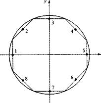
We choose to cover the body with eight panels of equal length, as shown in Figure 3.41. This choice is arbitrary; however, experience has shown that, for the case of a circular cylinder, the arrangement shown in Figure 3.41 provides sufficient accuracy. The panels are numbered from 1 to 8, and the control points are shown by the dots in the center of each panel.
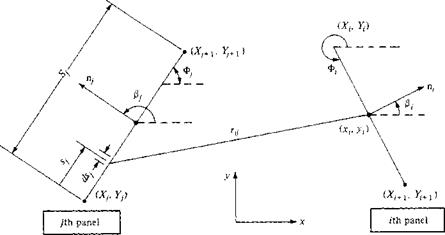
Let us evaluate the integrals which appear in Equation (3.153). Consider Figure 3.42, which illustrates two arbitrary chosen panels. In Figure 3.42, (x,. y,) are the coordinates of the
|
Figure 3.41 Source panel distribution around a circular cylinder. |
|
Figure 3.42 Geometry required for the evaluation of Іц. |
control point of the ith panel and (xh yj) are the running coordinates over the entire jth panel. The coordinates of the boundary points for the і th panel are (X, , Yt) and (Xi+1, F,+i); similarly, the coordinates of the boundary points for the jth panel are (Ху, У,) and (XJ+] In this
problem, Vcc is in the x direction; hence, the angles between the x axis and the unit vectors n, and itj are ft and ft, respectively. Note that, in general, both ft and ft vary from 0 to 2л Recall that the integral ft; is evaluated at the (th control point and the integral is taken over the complete jth panel:
|
|
|
|
|
|
|
|
|
|
|
|
|
|
Substituting the values for the X’s obtained into Equation (3.157), we see that the equation is identically satisfied.
The velocity at the control point of the ith panel can be obtained from Equation (3.156). In that equation, the integral over the jth panel is a geometric quantity which is evaluated in a similar manner as before. The result is
With the integrals in Equation (3.156) evaluated by Equation (3.165), and with the values for 7-і, 7-2,. • •, 7.8 obtained above inserted into Equation (3.156), we obtain the velocities Vi, V2,…, Vs. In turn, the pressure coefficients Cp 1, Cp>2,…, Cp, g are obtained directly from
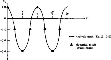
Results for the pressure coefficients obtained from this calculation are compared with the exact analytical result, Equation (3.101) in Figure 3.43. Amazingly enough, in spite of the relatively crude paneling shown in Figure 3.41, the numerical pressure coefficient results are excellent.


