Numerical Solutions—Computational Fluid Dynamics (CFD)
The other general approach to the solution of the governing equations is numerical. The advent of the modem high-speed digital computer in the last third of the twentieth century has revolutionized the solution of aerodynamic problems and has given rise to a whole new discipline—computational fluid dynamics. Recall that the basic governing equations of continuity, momentum, and energy derived in this chapter are either in integral or partial differential form. In Anderson, Computational Fluid Dynamics: The Basics With Applications, McGraw-Hill, 1995, computational fluid dynamics is defined as “the art of replacing the integrals or the partial derivatives (as the case may be) in these equations with discretized algebraic forms, which in turn are solved to obtain numbers for the flow field values at discrete points in time and/or space.” The end product of computational fluid dynamics (frequently identified by the acronym CFD) is indeed a collection of numbers, in contrast to a closed-form analytical solution. However, in the long run, the objective of most engineering analyses, closed form or otherwise, is a quantitative description of the problem, i. e., numbers.
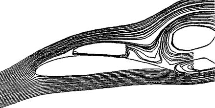
The beauty of CFD is that it can deal with the full non-linear equations of continuity, momentum, and energy, in principle, without resorting to any geometrical or physical approximations. Because of this, many complex aerodynamic flow fields have been solved by means of CFD which had never been solved before. An example of this is shown in Figure 2.40. Here we see the unsteady, viscous, turbulent, compressible, separated flow field over an airfoil at high angle of attack (14° in the case
|
Figure 3.40 Calculated streamline pattern for separated flow over an airfoil. Re = 300,000, = 0.5, angle of attack =14°. |
shown), as obtained from Reference 56. The freestream Mach number is 0.5, and the Reynolds number based on the airfoil chord length (distance from the front to the back edges) is 300,000. An instantaneous streamline pattern that exists at a certain instant in time is shown, reflecting the complex nature of the separated, recirculating flow above the airfoil. This flow is obtained by means of a CFD solution of the two-dimensional, unsteady continuity, momentum, and energy equations, including the full effects of viscosity and thermal conduction, as developed in Sections 2.4, 2.5, and 2.7, without any further geometrical or physical simplifications. The equations with all the viscosity and thermal conduction terms explicitly shown are developed in Chapter 15; in this form, they are frequently labeled as the Navier-Stokes equations. There is no analytical solution for the flow shown in Figure 2.40; the solution can only be obtained by means of CFD.
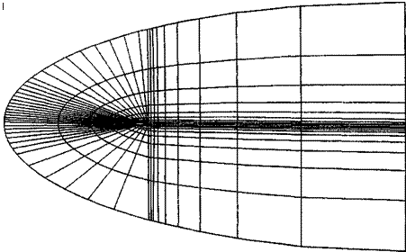
Let us explore the basic philosophy behind CFD. Again, keep in mind that CFD solutions are completely numerical solutions, and a high-speed digital computer must be used to carry them out. In a CFD solution, the flow field is divided into a number of discrete points. Coordinate lines through these points generate a grid, and the discrete points are called grid points. The grid used to solve the flow field shown in Figure 2.40 is given in Figure 2.41; here, the grid is wrapped around the airfoil, which is seen as the small white speck in the center-left of the figure, and the grid extends a very large distance out from the airfoil. This large extension of the grid into the main stream of the flow is necessary for a subsonic flow, because disturbances in a subsonic flow physically feed out large distances away from the body. We will learn why in subsequent chapters. The black region near the airfoil is simply the computer graphics way of showing a very large number of closely spaced grid points near the airfoil, for better definition of the viscous flow near the airfoil. The flow held properties, such as p, p, u, v, etc. are calculated just at the discrete grid points, and nowhere
 |
else, by means of the numerical solution of the governing flow equations. This is an inherent property that distinguishes CFD solutions from closed-form analytical solutions. Analytical solutions, by their very nature, yield closed-form equations that describe the flow as a function of continuous time and/or space. So we can pick any one of the infinite number of points located in this continuous space, feed the coordinates into the closed-form equations, and obtain the flow variables at that point. Not so with CFD, where the flow-field variables are calculated only at discrete grid points. For a CFD solution, the partial derivatives or the integrals, as the case may be, in the governing flow equations are discretized, using the flow-field variables at grid points only.
How is this discretization carried out? There are many answers to this equation. We will look at just a few examples, to convey the ideas.
Let us consider a partial derivative, such as du/dx. How do we discretize this partial derivative? First, we choose a uniform rectangular array of grid points as shown in Figure 2.42. The points are identified by the index і in the x direction, and the index j in the у direction. Point P in Figure 2.42 is identified as point (i, j). The value of the variable и at point j is denoted by и, j. The value of и at the point immediately to the right of P is denoted by u,41,; and that immediately to the left of P by Ui-ij. The values of и at the points immediately above and below point P are denoted by Uij+i and respectively. And so forth. The grid points in the x
direction are separated by the increment Ax, and the у direction by the increment Ay. The increments Ax and Ay must be uniform between the grid points, but Ax can be
Figure 2.42 An array of grid points in a uniform, rectangular grid.
 |
|||
a different value than Ay. To obtain a discretized expression for 3u/dx evaluated at point P, we first write a Taylors series expansion for m,_ L ; expanded about point P as:
Solving Equation (2.166) (Эм/Эх),-.,-, we have
Equation (2.167) is still a mathematically exact relationship. However, if we choose to represent (Эм/Эх); j just by the algebraic term on the right-hand side, namely,
![]() M j _|_ ] j LI j j
M j _|_ ] j LI j j
—– 1——- — Forward difference [2.1 68]
Ax
then Equation (2.168) represents an approximation for the partial derivative, where the error introduced by this approximation is the truncation error, identified in Equation
(2.167) . Nevertheless, Equation (2.168) gives us an algebraic expression for the partial derivative; the partial derivative has been discretized because it is formed by the values m/+i j and n,. / at discrete grid points. The algebraic difference quotient in Equation (2.168) is called a forward difference, because it uses information ahead of joint (/, j), namely ui+[ j. Also, the forward difference given by Equation (2.168) has first-order accuracy because the leading term of the truncation error in Equation
(2.167) has Ax to the first power.
Equation (2.168) is not the only discretized form for (du/dx)ij. For example, let us write a Taylors series expansion for Uj-j expanded about point P as
I (du , л л I (д2ц (-~Ax’>2 , (93“ (~A*)3
![]()
![]() = Щ.1 + (j-x) (-^) + (ailj – y-
= Щ.1 + (j-x) (-^) + (ailj – y-
 |
||||
[2.169]
 Rearward difference
Hence, we can represent the partial derivative by the rearward difference shown in Equation (2.170), namely,
|
( |
Эи и; ; — и,_і і _ _
— ) = — ———— — Rearward difference [2.171]
Э xJij Ax
Equation (2.171) is an approximation for the partial derivative, where the error is given by the truncation error labeled in Equation (2.170). The rearward difference given by Equation (2.171) has first-order accuracy because the leading term in the truncation error in Equation (2.170) has Ax to the first power. The forward and rearward differences given by Equations (2.168) and (2.171), respectively, are equally valid representations of (du/dx)jj, each with first-order accuracy.
In most CFD solutions, first-order accuracy is not good enough; we need a discretization of (du/dx)jj that has at least second-order accuracy. This can be obtained by subtracting Equation (2.169) from Equation (2.166), yielding
Solving Equation (2.172) for (du/dx)ij, we have

![]() /Эи Ui—j
/Эи Ui—j
3x / ■ . 2 Ax
4 7 C] ————- — —— ■
Central difference
Hence, we can represent the partial derivative by the central difference shown in Equation (2.173), namely
Examining Equation (2.173), we see that the central difference expression given in Equation (2.174) has second-order accuracy, because the leading term in the truncation error in Equation (2.173) has (Ax)2. For most CFD solutions, second-order accuracy is sufficient.
So this is how it works—this is how the partial derivatives that appear in the governing flow equations can be discretized. There are many other possible discretized
![]()
|
|
|
|
|
This example is a simple illustration of how a CFD solution to a given flow can be set up, in this case for an unsteady, one-dimensional flow. Note that the unknown velocity and internal energy at grid point і at time t + At can be calculated in the same manner, writing the appropriate difference equation representations for the x component of the momentum equation, Equation (2.113a), and the energy equation, Equation (2.114).
The above example looks very straightforward, and indeed it is. It is given here only as an illustration of what is meant by a CFD technique. However, do not be misled. Computational fluid dynamics is a sophisticated and complex discipline. For example, we have said nothing here about the accuracy of the final solutions, whether or not a certain computational technique will be stable (some attempts at obtaining numerical solutions will go unstable—blow up—during the course of the calculations), and how much computer time a given technique will require to obtain the flow-field solution. Also, in our discussion we have given examples of some relatively simple grids. The generation of an appropriate grid for a given flow problem is frequently a challenge, and grid generation has emerged as a subdiscipline in its own right within CFD. For these reasons, CFD is usually taught only in graduate-level courses in most universities. However, in an effort to introduce some of the basic ideas of CFD at the undergraduate level, I have written a book, Reference 64, intended to present the subject at the most elementary level. Reference 64 is intended to be read before students go on to the more advanced books on CFD written at the graduate level. In the present book, we will, from time-to-time, discuss some applications of
CFD as part of the overall fundamentals of aerodynamics. However, this book is not about CFD; Reference 64 is.


