PARA WINGS
Parawings are a form of delta wings in the sense that their planform has the delta slope; however, these lifting surfaces with a parachutelike tension structure are completely different. In this case the wing surface slope is maintained by the balance of forces between the airload on the surfaces and the tension in the supporting structure. These wings have been considered for use for a large variety of tasks from hang type gliders to wings for the recovery of space vehicles (14,a). The flexibility of the structure and its capability of being folded broaden the potential uses of parawings so that a brief discussion of their characteristics is desirable.
|
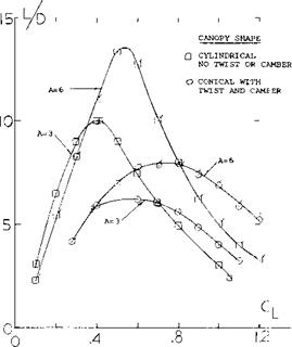
Figure 34. Lift-drag characteristics of two-lobed parawings. |
Lift Characteristics. The lifting characteristics of parawings depend on the type of canopy used and the aspect ratio. Typical test results (14,d) are given on figure 33 for wings with both types of canopies. The lift coefficient is based on the area of the flat wing pattern. The most striking difference between the two types of wings is the angle of attack for a given lift coefficient. Much larger angles are needed for the same lift coefficient with the conical wing. In the case of the A = 6 wings, CL* are nearly the same. At A = 3 the CLX of the conical wing is slightly better than the cylindrical wing. At the lower values of angle of attack the conical wing is limited by flutter at the trailing edges. This occurs at lift coefficients below.4 as indicated.
The effective shape of the conical wing results in a large variation of twist between the inboard and outboard sections so that the wing tip is operating at a negative lift at moderate lift coefficients. The twist or washout can be eliminated in the case of the cylindrical wing, which leads to tip stalling as CjLX is approached. The difference in the local angle of attack in the case of the two types of canopies determines the difference in the stalling characteristics and the lift drag ratio.
Longitudinal Moment. The variation of the pitching moment is given on figure 33. These data indicate that the wings will have a negative pitching moment at zero angle of attack so that for typical parawing applications the center of gravity must be located well below the wing to achieve trim and stability. In the normal operating range with such an arrangement good positive stability is obtained. However, at both the low and high lift coefficient negative stability is obtained which can lead to an end over end tumbling motion (14,b).
![]()
Geometric Characteristics. The parawing can be designed in many forms as discussed in (14,b), however, only the two-lobed type illustrated in figure 32 will be considered here. As noted in the figure, the wing has a central keel with two straight or curved booms to form the leading edges. The canopies are generally formed as a conical or cylindrical shape as illustrated, and the booms are spread by a bar that also serves to support the load. The shape of the trailing edge will be determined by the sweep of the flat pattern angle TV 0 and ^ie actual sweep angle of the boom. Although rigid members are considered for the booms and keel, a pension structure can be used to improve the storage characteristics. In this case a balance must be made of the forces to obtain the shape needed flor flight and control.
Lift-Drag Characteristics. At a given aspect ratio the canopy shape is the major factor influencing the lift-drag ratio that can be obtained with parawings, as illustrated on figure 34. For wings with the same aspect ratio the cylindrical shape gives a large improvement in the lift-drag ratio over that obtained with the conical shape. This is due to the improved load distribution resulting from the zero wing twist distribution. The improvement in load distribution almost doubles the lift-drag ratio of the wing, figure 34. With the use of a small degree of washout further improvements in L/Dmax can be obtained along with СцЛ.


