Pathlines, Streamlines, and Streaklines
of a Flow
In addition to knowing the density, pressure, temperature, and velocity fields, in aerodynamics we like to draw pictures of “where the flow is going.” To accomplish this, we construct diagrams of pathlines and/or streamlines of the flow. The distinction between pathlines and streamlines is described in this section.
Consider an unsteady flow with a velocity field given by V = V(x, y, z, t). Also, consider an infinitesimal fluid element moving through the flow field, say, element A as shown in Figure 2.25a. Element A passes through point 1. Let us trace the path
of element A as it moves downstream from point 1, as given by the dashed line in Figure 2.25a. Such a path is defined as the pathline for element A. Now, trace the path of another fluid element, say, element В as shown in Figure 2.25b. Assume that element В also passes through point 1, but at some different time from element A. The pathline of element В is given by the dashed line in Figure 2.25b. Because the flow is unsteady, the velocity at point 1 (and at all other points of the flow) changes with time. Hence, the pathlines of elements A and В are different curves in Figure 2.25a and b. In general, for unsteady flow, the pathlines for different fluid elements passing through the same point are not the same.
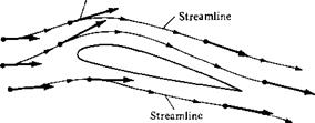
In Section 1.4, the concept of a streamline was introduced in a somewhat heuristic manner. Let us be more precise here. By definition, a streamline is a curve whose tangent at any point is in the direction of the velocity vector at that point. Streamlines are illustrated in Figure 2.26. The streamlines are drawn such that their tangents at every point along the streamline are in the same direction as the velocity vectors at those points. If the flow is unsteady, the streamline pattern is different at different times because the velocity vectors are fluctuating with time in both magnitude and direction.
In general, streamlines are different from pathlines. You can visualize a pathline as a time-exposure photograph of a given fluid element, whereas a streamline pattern is like a single frame of a motion picture of the flow. In an unsteady flow, the streamline pattern changes; hence, each “frame” of the motion picture is different.
However, for the case of steady flow (which applies to most of the applications in this book), the magnitude and direction of the velocity vectors at all points are fixed, invariant with time. Hence, the pathlines for different fluid elements going through the same point are the same. Moreover, the pathlines and streamlines are identical. Therefore, in steady flow, there is no distinction between pathlines and streamlines;
|
Velocity vector
Figure 3.36 Streamlines. |
|
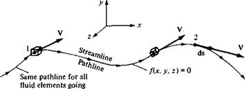
through point 1 Figure 3.37 For steady flow, streamlines and pathlines are the same. |
they are the same curves in space. This fact is reinforced in Figure 2.27, which illustrates the fixed, time-invariant streamline (pathline) through point 1. In Figure 2.27, a given fluid element passing through point 1 traces a pathline downstream. All subsequent fluid elements passing through point 1 at later times trace the same pathline. Since the velocity vector is tangent to the pathline at all points on the pathline for all times, the pathline is also a streamline. For the remainder of this book, we deal mainly with the concept of streamlines rather than pathlines; however, always keep in mind the distinction described above.
Question: Given the velocity field of a flow, how can we obtain the mathematical equation for a streamline? Obviously, the streamline illustrated in Figure 2.27 is a curve in space, and hence it can be described by the equation f(x, y,z) =0. How can we obtain this equation? To answer this question, let ds be a directed element of the streamline, such as shown at point 2 in Figure 2.27. The velocity at point 2 is V, and by definition of a streamline, V is parallel to ds. Hence, from the definition of the vector cross product [see Equation (2.4)],
ds x V = 0 I [3.115]
Equation (2.115) is a valid equation for a streamline. To put it in a more recognizable form, expand Equation (2.115) in cartesian coordinates:
Equations (2.117a to c) are differential equations for the streamline. Knowing u, v, and w as functions of x, y, and z, Equations (2.117a to c) can be integrated to yield the equation for the streamline: fix, y, z.) = 0.
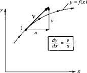
To reinforce the physical meaning of Equations (2.117a to c), consider a streamline in two dimensions, as sketched in Figure 2.28a. The equation of this streamline is у = fix). Hence, at point 1 on the streamline, the slope is dyjdx. However, V with x and у components и and v, respectively, is tangent to the streamline at point 1. Thus, the slope of the streamline is also given by v/u, as shown in Figure 2.26. Therefore,
[2.1 18]
|
Equation (2.118) is a differential equation for a streamline in two dimensions. From Equation (2.118),
v dx — и dy = 0
which is precisely Equation (2.117c). Therefore, Equations (2.117a to c) and (2.118) simply state mathematically that the velocity vector is tangent to the streamline.
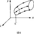
A concept related to streamlines is that of a streamtube. Consider an arbitrary closed curve C in three-dimensional space, as shown in Figure 2.28b. Consider the streamlines which pass through all points on C. These streamlines form a tube in space as sketched in Figure 2.28b; such a tube is called a streamtube. For example, the walls of an ordinary garden hose form a streamtube for the water flowing through the hose. For a steady flow, a direct application of the integral form of the continuity equation [Equation (2.53)] proves that the mass flow across all cross sections of a streamtube is constant. (Prove this yourself.)
 Consider the velocity field given by и = y/(x2 + y2) and v = —x/(x2 + y2). Calculate the equation of the streamline passing through the point (0, 5).
Solution
From Equation (2.118), dy/dx = v/u = —x/y, and
ydy = —x dx
Integrating, we obtain
+ c
where c is a constant of integration.
For the streamline through (0, 5), we have
52 = 0 + c or c — 25
Thus, the equation of the streamline is
Note that the streamline is a circle with its center at the origin and a radius of 5 units.
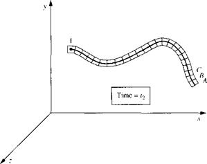
Streamlines are by far the most common method used to visualize a fluid flow. In an unsteady flow it is also useful to track the path of a given fluid element as it moves through the flow field, i. e., to trace out the pathline of the fluid element. However, separate from the ideas of a streamline and a pathline is the concept of a streakline. Consider a fixed point in a flow field, such as point 1 in Figure 2.29. Consider all the individual fluid elements that have passed through point 1 over a given time interval t2 — q. These fluid elements, shown in Figure 2.29, are connected with each other, like a string of elephants connected trunk-to-tail. Element A is the fluid element that passed through point 1 at time q. Element В is the next element that passed through point 1, just behind element A. Element C is the element that passed through point 1 just behind element B, and so forth. Figure 2.29 is an illustration, made at time t2, which shows all the fluid elements that have earlier passed through point 1 over the time interval (t2 — q). The line that connects all these fluid elements is, by definition, a
|
Figure 2.29 Illustration of a streakline through point I. |
streakline. We can more concisely define a streakline as the locus of fluid elements which have earlier passed through a prescribed point. To help further visualize the concept of a streakline, imagine that we are constantly injecting dye into the flow field at point 1. The dye will flow downstream from point 1, forming a curve in the x, y, z space in Figure 2.29. This curve is the streakline shown in Figure 2.29. A photograph of a streakline in the flow of water over a circular cylinder is shown in Figure 3.48. The white streakline is made visible by white particles that are constantly formed by electrolysis near a small anode fixed on the cylinder surface. These white particles subsequently flow downstream forming a streakline.
For a steady flow, pathlines, streamlines, and streaklines are all the same curves. Only in an unsteady flow are they different. So for steady flow, which is the type of flow mainly considered in this book, the concepts of a pathline, streamline, and streakline are redundant.


