Prandtl’s Classical Lifting-Line Theory
The first practical theory for predicting the aerodynamic properties of a finite wing was developed by Ludwig Prandtl and his colleagues at Gottingen, Germany, during the period 1911-1918, spanning World War I. The utility of Prandtl’s theory is so great
that it is still in use today for preliminary calculations of finite-wing characteristics. The purpose of this section is to describe Prandtl’s theory and to lay the groundwork for the modern numerical methods described in subsequent sections.
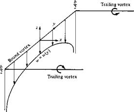
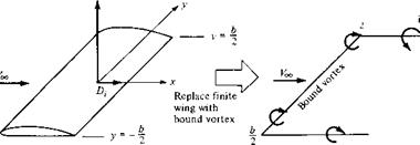
Prandtl reasoned as follows. A vortex filament of strength Г that is somehow bound to a fixed location in a flow—a so-called bound vortex—will experience a force L = Poo ‘oc Г from the Kutta-Joukowski theorem. This bound vortex is in contrast to a free vortex, which moves with the same fluid elements throughout a flow. Therefore, let us replace a finite wing of span b with a bound vortex, extending from у = —b/2 to у = b/2, as sketched in Figure 5.10. However, due to Helmholtz’s theorem, a vortex filament cannot end in the fluid. Therefore, assume the vortex filament continues as two free vortices trailing downstream from the wing tips to infinity, as also shown in Figure 5.10. This vortex (the bound plus the two free) is in the shape of a horseshoe, and therefore is called a horseshoe vortex.
A single horseshoe vortex is shown in Figure 5.11. Consider the down wash w induced along the bound vortex from — b/2 to b/2 by the horseshoe vortex. Examining Figure 5.11, we see that the bound vortex induces no velocity along itself; however, the two trailing vortices both contribute to the induced velocity along the bound vortex, and both contributions are in the downward direction. Consistent with the xyz coordinate system in Figure 5.11, such a downward velocity is negative; that is, w (which is in the г direction) is a negative value when directed downward and a positive value when directed upward. If the origin is taken at the center of the bound vortex, then the velocity at any point у along the bound vortex induced by the trailing semi-infinite vortices is, from Equation (5.11),
In Equation (5.12), the first term on the right-hand side is the contribution from the left trailing vortex (trailing from —b/2), and the second term is the contribution from the right trailing vortex (trailing from b/2). Equation (5.12) reduces to
 [5.13]
![]()
![]()

![]()
![]()
![]()
 4 Free-trailing vortex
|
Figure 5.1 1 Downwash distribution along the у axis for a single horseshoe vertex. |
This variation of w(y) is sketched in Figure 5.11. Note that w approaches —oo as у approaches —b/2 or b/2.
The downwash distribution due to the single horseshoe vortex shown in Figure 5.11 does not realistically simulate that of a finite wing; the downwash approaching an infinite value at the tips is especially disconcerting. During the early evolution of finite-wing theory, this problem perplexed Prandtl and his colleagues. After several years of effort, a resolution of this problem was obtained which, in hindsight, was simple and straightforward. Instead of representing the wing by a single horseshoe vortex, let us superimpose a large number of horseshoe vortices, each with a different length of the bound vortex, but with all the bound vortices coincident along a single line, called the lifting line. This concept is illustrated in Figure 5.12, where only three horseshoe vortices are shown for the sake of clarity. In Figure 5.12, a horseshoe vortex of strength <іГі is shown, where the bound vortex spans the entire wing from —b/2 to b/2 (from point A to point F). Superimposed on this is a second horseshoe vortex of strength (ІГ2, where its bound vortex spans only part of the wing, from point В to point E. Finally, superimposed on this is a third horseshoe vortex of strength tf Г3, where its bound vortex spans only the part of the wing from point C to point D. Asa result, the circulation varies along the line of bound vortices—the lifting line defined above. Along A В and EF, where only one vortex is present, the circulation is dV . However, along BC and DE, where two vortices are superimposed, the circulation is the sum of their strengths dV]+dr2- Along CD, three vortices are superimposed, and hence the circulation is dVi + dT2 + dT3. This variation of Г along the lifting line is denoted by the vertical bars in Figure 5.12. Also, note from Figure 5.12 that we now have a series of trailing vortices distributed over the span, rather than just two vortices trailing downstream of the tips as shown in Figure 5.11. The series of
|
|
|
|
|
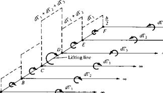
trailing vortices in Figure 5.12 represents pairs of vortices, each pair associated with a given horseshoe vortex. Note that the strength of each trailing vortex is equal to the change in circulation along the lifting line.
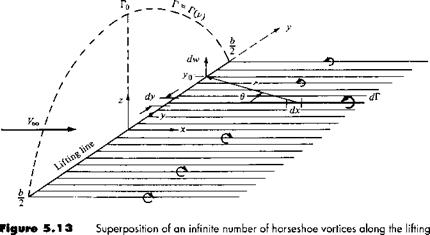
Let us extrapolate Figure 5.12 to the case where an infinite number of horseshoe vortices are superimposed along the lifting line, each with a vanishingly small strength dV. This case is illustrated in Figure 5.13. Note that the vertical bars in Figure 5.12 have now become a continuous distribution of Г(у) along the lifting line in Figure 5.13. The value of the circulation at the origin is Г0. Also, note that the finite number of trailing vortices in Figure 5.12 have become a continuous vortex sheet trailing downstream of the lifting line in Figure 5.13. This vortex sheet is parallel to the direction of Too. The total strength of the sheet integrated across the span of the wing is zero, because it consists of pairs of trailing vortices of equal strength but in opposite directions.
Let us single out an infinitesimally small segment of the lifting line dy located at the coordinate у as shown in Figure 5.13. The circulation at у is Г(у), and the change in circulation over the segment dy is dV = (dГ/dy) dy. In turn, the strength of the trailing vortex at у must equal the change in circulation dГ along the lifting line; this is simply an extrapolation of our result obtained for the strength of the finite trailing vortices in Figure 5.12. Consider more closely the trailing vortex of strength dГ which intersects the lifting line at coordinate y, as shown in Figure 5.13. Also consider the arbitrary location yo along the lifting line. Any segment of the trailing vortex dx will induce a velocity at yo with a magnitude and direction given by the Biot-Savart law, Equation (5.5). In turn, the velocity dw at yo induced by the entire semi-infinite trailing vortex located at у is given by Equation (5.11), which in terms of the picture given in Figure 5.13 yields
|
|
|
The minus sign in Equation (5.14) is needed for consistency with the picture shown in Figure 5.13; for the trailing vortex shown, the direction of dw at yo is upward and hence is a positive value, whereas Г is decreasing in the у direction, making dV/dy a negative quantity. The minus sign in Equation (5.14) makes the positive dw consistent with the negative dV/dy.
The total velocity w induced at y(l by the entire trailing vortex sheet is the summation of Equation (5.14) over all the vortex filaments, that is, the integral of Equation
(5.14)
from – b/2tob/2:
Equation (5.15) is important in that it gives the value of the downwash at y(l due to all the trailing vortices. (Keep in mind that although we label w as downwash, w is treated as positive in the upward direction in order to be consistent with the normal convention in an xyz rectangular coordinate system.)
Pause for a moment and assess the status of our discussion so far. We have replaced the finite wing with the model of a lifting line along which the circulation Г (у) varies continuously, as shown in Figure 5.13. In turn, we have obtained an expression for the downwash along the lifting line, given by Equation (5.15). However, our central problem still remains to be solved; that is, we want to calculate T(y) for a given finite wing, along with its corresponding total lift and induced drag. Therefore, we must press on.
Return to Figure 5.4, which shows the local airfoil section of a finite wing. Assume this section is located at the arbitrary spanwise station yo. From Figure 5.4,
![]()
![]()
the induced angle of attack a, is given by
-w(yp)
[Note in Figure 5.4 that w is downward, and hence is a negative quantity. Since a, in Figure 5.4 is positive, the negative sign in Equation (5.16) is necessary for consistency.] Generally, w is much smaller than VJ, and hence a, is a small angle, on the order of a few degrees at most. For small angles, Equation (5.16) yields
that is, an expression for the induced angle of attack in terms of the circulation distribution Г(у) along the wing.
Consider again the effective angle of attack aeff, as shown in Figure 5.4. As explained in Section 5.1, oy-n is the angle of attack actually seen by the local airfoil section. Since the downwash varies across the span, then оуц is also variable; ауп = ateff (jo)• The lift coefficient for the airfoil section located at у = y0 is
Ci = ao[aeff(>’o) — «/.= ol = 27r[aeff(yo) — аТ=о] [5.19]
![]() In Equation (5.19), the local section lift slope ao has been replaced by the thin airfoil theoretical value of 2n-(rad-1). Also, for a wing with aerodynamic twist, the angle of zero lift ai=o in Equation (5.19) varies with vy. If there is no aerodynamic twist, aL=0 is constant across the span. In any event, aL=0 is a known property of the local airfoil sections. From the definition of lift coefficient and from the Kutta-Joukowski theorem, we have, for the local airfoil section located at yo.
In Equation (5.19), the local section lift slope ao has been replaced by the thin airfoil theoretical value of 2n-(rad-1). Also, for a wing with aerodynamic twist, the angle of zero lift ai=o in Equation (5.19) varies with vy. If there is no aerodynamic twist, aL=0 is constant across the span. In any event, aL=0 is a known property of the local airfoil sections. From the definition of lift coefficient and from the Kutta-Joukowski theorem, we have, for the local airfoil section located at yo.
L’ = {pccV£,c(yo)ci = РооЕооГ(уо) [5.20]
From Equation (5.20), we obtain
![]() _ 2Г (yo)
_ 2Г (yo)
C> V’coc(y0)
Substituting Equation (5.21) into (5.19) and solving for оуц, we have
The above results come into focus if we refer to Equation (5.1):
![]() «eff = a – a.
«eff = a – a.
![]()
|
|||
|
|||
|
|||
|
|||
|
|||
|
|||
|
|||
|
|||
 |
|||
|
|
||
An important geometric property of a finite wing is the aspect ratio, denoted by AR and defined as
Hence, Equation (5.41) becomes
Equation (5.42) is a useful expression for the induced angle of attack, as shown below.
The induced drag coefficient is obtained from Equation (5.30), noting that a, is constant:
Substituting Equations (5.40) and (5.42) into (5.42a), we obtain
nb / CL 2VqcSCl 2 Voo S tr AR ) bn
Equation (5.43) is an important result. It states that the induced drag coefficient is directly proportional to the square of the lift coefficient. The dependence of induced drag on the lift is not surprising, for the following reason. In Section 5.1, we saw that induced drag is a consequence of the presence of the wing-tip vortices, which in turn are produced by the difference in pressure between the lower and upper wing surfaces. The lift is produced by this same pressure difference. Hence, induced drag is intimately related to the production of lift on a finite wing; indeed, induced drag is frequently called the drag due to lift. Equation (5.43) dramatically illustrates this point. Clearly, an airplane cannot generate lift for free; the induced drag is the price for the generation of lift. The power required from an aircraft engine to overcome the induced drag is simply the power required to generate the lift of the aircraft. Also, note that because Co. і cx C, the induced drag coefficient increases rapidly as CL increases and becomes a substantial part of the total drag coefficient when Cl is high (e. g., when the airplane is flying slowly such as on takeoff or landing). Even at relatively high cruising speeds, induced drag is typically 25 percent of the total drag.
Another important aspect of induced drag is evident in Equation (5.43); that is, Co. і is inversely proportional to aspect ratio. Hence, to reduce the induced drag, we want a finite wing with the highest possible aspect ratio. Wings with high and low aspect ratios are sketched in Figure 5.14. Unfortunately, the design of very high aspect ratio wings with sufficient structural strength is difficult. Therefore, the aspect ratio of a conventional aircraft is a compromise between conflicting aerodynamic and structural requirements. It is interesting to note that the aspect ratio of the 1903 Wright
|
|
|
|
|
|
|
|
|
|
|

![]()
Flyer was 6 and that today the aspect ratios of conventional subsonic aircraft range typically from 6 to 8. (Exceptions are the Lockheed U-2 high-altitude reconnaissance aircraft with AR = 14.3 and sailplanes with aspect ratios in the 10 to 22 range.)
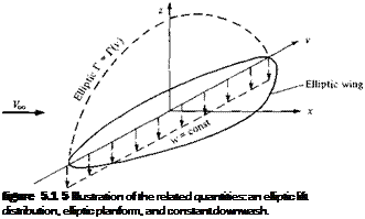
Another property of the elliptical lift distribution is as follows. Consider a wing with no geometric twist (i. e., a is constant along the span) and no aerodynamic twist (i. e., a/ =o is constant along the span). From Equation (5.42), we have seen that o’, is constant along the span. Hence, — a — cti is also constant along the span. Since the local section lift coefficient q is given by
ci = a0(aeS – aL=o)
then assuming that ao is the same for each section (ag = 2л from thin airfoil theory), ci must be constant along the span. The lift per unit span is given by
![]() L'(y) = qcaCCi
L'(y) = qcaCCi
Solving Equation (5.44) for the chord, we have
In Equation (5.45), q00 and c; are constant along the span. However, L'(y) varies elliptically along the span. Thus, Equation (5.45) dictates that for such an elliptic lift distribution, the chord must vary elliptically along the spam, that is, for the conditions given above, the wing planform is elliptical.
The related characteristics—the elliptic lift distribution, the elliptic planform, and the constant downwash—are sketched in Figure 5.15. Although an elliptical lift distribution may appear to be a restricted, isolated case, in reality it gives a reasonable approximation for the induced drag coefficient for an arbitrary finite wing. The form
 |
of Сил given by Equation (5.43) is only slightly modified for the general case. Let us now consider the case of a finite wing with a general lift distribution.


