Pressure Gradients and Boundary-Layer Profiles: A Qualitative Assessment
To discuss the effect of a streamwise pressure gradient on the behavior of a boundary layer, it is necessary to examine the x-momentum boundary-layer equation, Eq. 8.37, with the pressure-gradient term included; namely:
Recalling that dp/dz = 0, dp/dx previously could have been written as dp/dx (i. e., as the total derivative) because p only changes in the direction parallel to the surface.
For convenience, we consider a flat plate installed in a curved nozzle, shown in Fig. 8.15, as a simplified model of a flow along a curved airfoil surface that is experiencing a pressure gradient.
For an incompressible flow, continuity demands that as the nozzle area decreases, the freestream velocity must increase (see Fig. 8.14a). The Bernoulli Equation may be written for the freestream flow to relate velocity changes to static-pressure changes. Recalling that the freestream impresses a pressure distribution on the boundary
![]() I* »
I* »
(a) favorable pressure gradient (b) adverse pressure gradient
Figure 8.15. Flat-plate boundary layer with streamwise pressure gradient.
layer, the Bernoulli Equation may be thought of as written for a streamline only at the outer edge of the boundary layer, where the velocity is Ue. Thus,
![]()
![]() 1 2
1 2
p + 2 pUe = constant.
Differentiating in the x-direction along a streamline:
dp dUe
dx+pU«d~=“■
Thus, in discussing a boundary layer, we may speak interchangeably about a stream- wise pressure gradient or an external-flow velocity gradient. In particular, the x-momentum equation, Eq. 8.83, may be written in an alternate form by replacing dp/dx with the expression from Eq. 8.86; namely:

![]() dU d u
dU d u
—r^+v~r. dx dz2
We continue the discussion in terms of a pressure gradient because it is more meaningful physically. The velocity-gradient substitution is used as a convenience because the pressure gradient is usually known in terms of the velocity distribution in the external flow field.
Considering Fig. 8.15a, the boundary layer on this plate is experiencing a decrease in static pressure in the streamwise direction (dp/dx < 0). This is called a favorable pressure gradient. Conversely, the boundary layer in Fig. 8.15b is experiencing an increasing static-pressure field with downstream distance, or (dp/dx > 0). This is called an adverse pressure gradient.
Without solving anything, we determine which conclusions we can draw regarding the behavior of a boundary-layer velocity profile with a pressure gradient. First, we write Eq. 8.70 at the surface where, by virtue of the boundary conditions, u = w = 0. At the wall, then:
Consider three different streamwise pressure gradients, first making the right side of Eq. 8.84 zero, then less than zero, and, finally, greater than zero. Examine the qualitative behavior of the variation in the slope of the velocity profile, du/dz, with distance, z, from the surface, as shown in Fig. 8.16. Recognize that for large z, the slope of the velocity profile must go to zero as the boundary-layer profile merges with the constant freestream velocity, Ue, at the edge of the boundary layer. Be careful: The graphs in Fig. 8.16 present the variation of the slope of the velocity profile with z, not the velocity profile itself.
Figure 8.16a represents a flat plate with zero pressure gradient. Eq. 8.74 states that at z = 0, the derivative of du/dz is zero. The second derivative of u being zero implies that the velocity profile u(z) has an inflection point at z = 0. The slope of the profile then continually decreases and approaches zero for large z, that is, at large z, u ~ constant and, hence, du/dz ~ 0. This corresponds to the behavior of the Blasius boundary-layer (i. e., zero pressure gradient) profile, discussed previously.
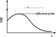 |
Figure 8.16. Variation of velocity-profile slope with pressure gradient.
Figure 8.16b corresponds to a favorable pressure gradient. Then, d2u/dz2 < 0 at the wall, from Eq. 8.74, the slope of the velocity profile continually decreases with increasing z, and there is no inflection point in the profile.
Figure 8.16c corresponds to an adverse-pressure gradient. Here, the second derivative of the profile, d2u/dz2, must be positive at the wall, Eq. 8.88 and also d2u/dz2 must approach zero far from the wall, as discussed previously. However, this says that there must be an inflection point in the profile somewhere in between (i. e., at some z, d2u/dz2 = 0) and there is a reversal of profile curvature there. The argument is too elementary to be able to specify the value of z at which this happens, but a change in curvature in the profile must occur. The character of the pressure gradient thus has a profound effect on the boundary-layer velocity profile.
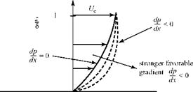
We examine the effect of a streamwise pressure gradient from another physical viewpoint. Consider a fluid particle moving streamwise in the boundary layer. By virtue of its movement, it possesses a certain momentum. If the pressure acting on the back of the particle is greater than that on the front (a favorable pressure gradient), then the unbalanced force accelerates the particle and increases its momentum. This increase in momentum has a more pronounced effect near the wall, where the particle momentum initially is small. A favorable pressure gradient thus makes the boundary-layer velocity profile more full near the wall, as illustrated in Fig. 8.17. This fullness increases for a stronger favorable pressure gradient. There is no inflection point in the profile, as expected from the previous discussion. Be careful when thinking about the slope of a boundary-layer velocity profile, du/dz! The student is used to thinking about slope expressions where u is the ordinate and z the abscissa, whereas boundary-layer convention plots z as ordinate and u as abscissa.
Figure 8.17. Velocity profile change with favorable pressure gradient.
 Now, we consider the same fluid particle in an adverse-pressure gradient. Here, the particle is working against an unbalanced force directed upstream and the particle loses momentum. Again, the effect is most noticeable near the wall, where the particle momentum is small, as shown in Fig. 8.18. Thus, the profile changes with an inflection point appearing, as previously discussed. If the adverse-pressure gradient becomes stronger, and as the adverse-pressure gradient persists, the velocity profile increasingly distorts and du/dz near the wall becomes increasingly smaller.
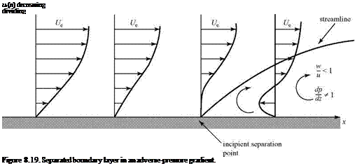
If the adverse-pressure gradient continues to a certain point, then ultimately the fluid particles very near the wall lose all of their momentum and a point is reached where, at the wall, both z = 0 and du/dz = 0. This is called the incipient separation point, as shown in Fig. 8.19. A separation streamline originates at the separation point and is a line of demarcation between the external flow and the “dead-air” flow in the separation region. Thus, if there is separation on a surface, the oncoming flow experiences a large apparent change in the geometry of the surface and it no longer proceeds in a direction parallel to the surface, as in an inviscid flow. Within the separated region, there is a flow reversal and vortices are formed. Notice that within the separated region, the point on the velocity profile where u = 0 must lie beneath the separation streamline so that the reversed flow can circulate within the region.
Within the separated region, the velocity-component ratio w/u is no longer small and the boundary-layer equations no longer hold. Likewise, dp/dz is no longer negligibly small. Depending on the pressure field, the separation streamline may bend back and reattach to the wall farther downstream, forming a separation bubble, or it may trail downstream to form a wake. Recall the inviscid-pressure distribution on the surface of a right-circular cylinder from Chapter 4. At 90° from the oncoming stream, the local velocity is 2У^ and the pressure is a minimum. Beyond that point, the surface pressure increases to a second stagnation point at 180°. However, in a viscous flow, the boundary layer on a cylinder separates soon after 90° because
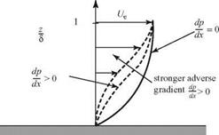 Figure 8.18. Velocity-profile change with adverse-pressure gradient.
 |
it experiences an adverse-pressure gradient and a wake forms downstream of the cylinder. The same general findings pertain to any bluff object.
It should be clear from this discussion that boundary-layer separation does not occur in the presence of a favorable pressure gradient. Separation is caused by an adverse pressure gradient. Furthermore, separation is to be avoided if possible because the dividing streamline greatly modifies the apparent shape of a carefully designed surface. That is, the intended pressure distribution is not achieved and the aerodynamic performance may be impaired. This usually means greatly increased drag and sometimes serious degradation of control and handling properties of a flight vehicle.
 |
This physical description of boundary-layer behavior in the presence of an adverse pressure gradient may be applied to the performance of an airfoil.
 |
It is clearly advantageous to delay or avoid separation. Consideration of the physical cause of separation in an adverse pressure gradient suggests that it is useful to make the boundary-layer profile “fuller,” which allows more of a momentum loss near the surface before incipient separation occurs. There are several ways to accomplish this as follows:
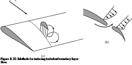
1. Make the boundary layer turbulent. As mentioned previously and as shown later in this chapter, the turbulent boundary layer has a fuller profile than the laminar one, as shown in Fig. 8.20a. Thus, separation is less likely but at the cost of greater frictional drag. In low-speed applications (e. g., high-performance sailplane design) it is common to use turbulators to purposely introduce transition to turbulence. This avoids the formation of “laminar separation bubbles” that represent a serious loss of aerodynamic efficiency. The turbulators often take the form of “zig-zag” tape, which is bonded to the surface in areas where it is desired to induce turbulent transition (e. g., near the aileron or flap hinge line). The mechanism by which the tape “trips” the boundary layer is not well understood, but it is clear that the irregular protrusion into the airflow creates vortices or eddies—vortical waves—that trigger the required transition to turbulent flow downstream of the tape.
2. Blow higher-energy air tangential to the surface prior to separation. This creates a distorted profile, shown in Fig. 8.20b, with much higher momentum near the surface. A blown flap is illustrated where air from the higher-pressure underside of the flap flows through a slot and energizes the boundary layer on the upper, lower-pressure side. This is a form of boundary-layer control. Generally,
considerable design complexity and, hence, cost are introduced by using tangential blowing because it implies a source for the high-energy flow along with the attendant ducting, injection surfaces, and control systems.
3. Use a vortex generator. This generator is a miniature wing or vane projecting vertically from the upper surface of a wing and at an angle of attack to the oncoming flow, as shown in Fig. 8.20c. The mechanism here is similar to that described in Method 1; that is, the formation of vortices to stimulate the creation of a fully turbulent unsteady boundary layer. A vortex is continuously shed at the tip of the vortex generator for precisely the same reason that it forms at the tip of a three-dimensional wing. This vortex sweeps higher-momentum air downward from the outer edge of the boundary layer to “energize” the low – momentum region of the boundary layer near the surface. Rows of such generators are sometimes seen on the upper surfaces of wings. For example, they are a familiar feature of the wing surfaces on certain commercial jet aircraft, such as the Boeing 757. Their main purpose in such cases usually is to ensure that flow separation does not affect the behavior of the flaps or other aerodynamic controls. Any measure that aids in the prevention of large-scale separation is an advantage; however, as we will see, a turbulent boundary layer causes increased skin-friction drag.
The possibility of flow separation also is incorporated into the design of flow devices. For example, the diffuser of a subsonic wind tunnel, which slows the flow after it passes through the test section, usually has a slowly increasing cross section (making for a long length) that as small an adverse pressure gradient as possible is imposed on the diffuser flow.
It is obviously important to study in more detail the features of viscous-boundary – layer flows with pressure gradients. Qualitative discussions of a few experimental findings hardly can provide enough information. It is useful to first attempt to extend the analysis used for the flat plate (i. e., the zero-pressure-gradient problem) to situations with a pressure gradient. In a famous paper, Falkner and Skan showed that the similarity method can be used for a restricted class of freestream velocities of the following form:
Ue(x) = U1xm,
where m can be 0, < 1, or >1 and U1 is a constant velocity-scaling parameter. This special case is discussed briefly in the next subsection. An approximate integral treatment for the case of a more general pressure gradient follows.
Similar Boundary-Layer Solutions with Arbitrary Pressure Gradients
Following the same general approach used for the Blasius problem, we introduce a dimensionless stream function, ¥, and similarity parameter, n, of the following form:
|
v(*. n) = |
![]() m +1
m +1
Ul
vx’
where the notation follows closely that used previously. If these expressions are used to rewrite the boundary-layer equation (Eq. 8.84), we find (as in the flat-plate problem) that the motion is now governed by an ordinary differential equation for the function f (n). This is the Falkner-Skan equation:
![]() f"’+ ff "+^m (i – f ‘2)=o,
f"’+ ff "+^m (i – f ‘2)=o,
m +1
where primes denote differentiation with respect to the boundary-layer coordinate, n, and solutions are possible only for certain ranges of values of m as already suggested. Note that Eq. 8.89 reduces to the Blasius equation for m = 0. Because the equation is nonlinear, it is clear that we might encounter problems of convergence or numerical instability. In particular, it is required that the pressure-gradient parameter:
![]() 2m m +1
2m m +1
must lie in a range for which there is no flow separation. It was found that flow separation occurs if в < -0.1988388, and numerical difficulties (e. g., failure to converge) are encountered in that pressure-gradient range.
The finite-difference numerical method introduced for solution of the Blasius equation can be used for the Falkner-Skan problem. Reducing the order by using g = f, the equation can be rewritten as:
g" + fg’ + P(1 + g2) = 0. (8.91)
As before, the second-order central difference equations can be used to represent the derivatives, and the result is linear in the unknown value of g. The nonlinear term, g2, can be converted to linear form by using a Taylor-series expansion. Expanding in the kth iteration from the known (or initial) value of g to the unknown or (k + 1)st level, we write:
( gf*1 f= 2gk gf*1-(g, k )2
Then, the finite-difference representation for the Falkner-Skan equation is:
As before, this can be rearranged into a convenient tridiagonal system:
and the solution procedure closely follows that described for the Blasius problem. An initial guess for gi is inserted and the corresponding f; is found from trapezoidal – rule integration. The equation is solved as many times as required to reach a prescribed level of convergence.
 |
Numerical solutions for several values of the pressure-gradient parameter, p, are shown in Fig. 8.21. For negative values of p, an inflection point exists in the parallel velocity profile (u versus n), a point that was deduced previously using a qualitatitive argument. For the separation value (about P = -0.199), the inflection point is farthest away from the wall. Also, for the higher positive values of the pressure gradient, the boundary layer is thinner, as we might expect. The vertical-velocity profile (v versus n) also is shown in Fig. 8.21. Notice that the result is scaled to the parameter U1 and the square root of the Re number based on the distance x from the leading edge of the surface. Also note the remarkable feature that for favorable pressure gradients (P > 0.1, approximately), the normal velocity component is less than zero; that is, the flow is toward the surface and the boundary layer is thinner. It was demonstrated that boundary-layer thickness decreases for values of p greater than 1. Because increased p corresponds to an increasingly favorable pressure gradient, we see that the effect is to make the boundary-layer thickness increasingly smaller.
Table 8.2 lists the values of displacement thickness, momentum thickness, wall – shear stress, and skin-friction coefficient as a function of p.


