Propulsion for supersonic flight
Intake design
Existing turbo-jet and turbo-fan designs will not accept supersonic flow at inlet, but by placing the engine in a suitably-shaped duct, it is possible to slow the air down to subsonic speeds before entry.
|
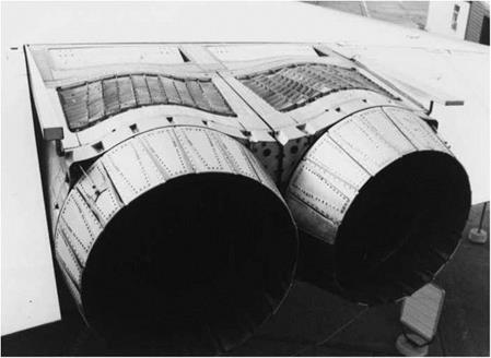
Fig. 6.32 The variable-geometry outlet nozzles and the louvres of the thrust reversers are seen in this view of the hot end of the Concorde engine installation |
At supersonic speeds, with the simple tubular ‘pitot’ type air intake, the flow has to decelerate through a detached normal shock. This results in considerable losses. Much higher efficiency is obtained if the flow is compressed through a series of oblique shocks. Figure 6.33 shows the intake system used on Concorde. The flow is compressed, and the speed reduced through a series of oblique shock waves, a region of shockless compression, and a weak normal shock. The intake geometry has to be varied in flight to match the Mach number of the approaching flow, and to capture the shock. Movable ramps are used for this purpose. Extra intake area is provided for flight at low subsonic speeds. Intakes of this type are classified as two-dimensional, and are used on a number of combat aircraft.
Note that part of the compression is provided by the shock wave produced by the wing. This shows the importance of integrating the design of the engine intake with that of the wing.
An alternative axi-symmetric arrangement is to use an axially movable or variable-geometry central bullet, as shown in Fig. 6.39. In the design depicted in this drawing, a combination of external and internal shock waves is shown. Axi-symmetric bullet-type intakes are used on the SR-71 Blackbird shown in
![]()
 Boundary layer Movable ramp
![]() Oblique
Oblique
shock waves shock system flow
Fig. 6.33 A two-dimensional type variable geometry intake for supersonic flight
This form of intake is used on Concorde. In supersonic cruise, the air is slowed down to subsonic speed and compressed through a series of oblique shocks and a region of shockless compression produced by the curved movable ramp (a) Subsonic configuration (b) Supersonic configuration
Fig. 6.40. Aircraft with side intakes may use two half axi-symmetric intakes, as on the F-104 (Fig. 8.8), or quarter versions, as on the F-111 (Fig. 6.35).
The design of supersonic intakes is an extremely complex subject, and further information will be found in Seddon and Goldsmith (1985) and Kuchemann (1978).
Although the variable geometry intake reduces losses due to shocks, it results in an increase in weight and complexity. A variety of fixed and variable intakes may be seen on modern combat aircraft. The Tornado (Fig. 3.15), and F-14 (Fig. 8.2) use two-dimensional variable geometry intakes, whereas a simpler fixed pitot type is used on the F-16.
The choice depends largely on the main combat role intended. The Tornado is designed for multi-role use which includes sustained supersonic flight, so that efficient supersonic cruising is necessary.
In the interests of avoiding strong radar reflections, ‘stealthy’ aircraft may have unusual inlet and exhaust arrangements, as shown in Fig. 6.34. These are not necessarily aerodynamically optimised.
|
Fig. 6.34 Design for stealth On the F-117A stealth fighter/bomber the intakes are concealed behind a radar absorbent grid. Thin two-dimensional exhaust nozzles are used, with the lower lip protruding so as to conceal the exhaust aperture. The use of flat-faceted surfaces helps to reduce the radar signature. The resulting shape, which has the appearance of being folded from a sheet of cardboard, must have presented a considerable challenge to the Lockheed aerodynamicists |


