Purpose and Principle of the Main Rotor – Tilt Control System
The main rotor tilt control is designed to control the collective and
cyclic pitch. This system is used to control the main rotor thrust force in magnitude and direction. Therefore, the tilt control is the most important unit of the helicopter control system. There are three types of main rotor tilt controls: ring, "spider," and crank types. The latter type of tilt
control is used only on two-rotor helicopters with side-by-side positioning of the rotors.
|
The |
ring type tilt control can be used on |
all helicopters. It includes |
|
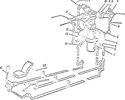
(Figure |
105): |
|
|
(1) |
movable ring (plate); |
|
|
(2) |
fixed ring; |
|
|
(3) |
slider; |
|
|
(4) |
universal hinge or cardan; |
|
|
(5) |
scissors or bellcrank; |
|
|
(6) |
vertical control rods. |
|
|
The movable ring of the tilt control rotates relative to the fixed ring. It is driven from the main rotor hub by means of a scissors. On the |
![]() movable ring there are levers which are connected with the blade pitch control horns by means of vertical links. The fixed ring is connected with the slider by means of a universal, which consists of a ring and two mutually perpendicular shafts. The universal permits the tilt control rings to deflect in any direction. If the plane of the rings is perpendicular to the main rotor shaft axis, when the movable ring rotates the vertical links will not have any vertical displacement and the blade pitch will not change. Consequently, in this case the rotor will not have any cyclic pitch change.
movable ring there are levers which are connected with the blade pitch control horns by means of vertical links. The fixed ring is connected with the slider by means of a universal, which consists of a ring and two mutually perpendicular shafts. The universal permits the tilt control rings to deflect in any direction. If the plane of the rings is perpendicular to the main rotor shaft axis, when the movable ring rotates the vertical links will not have any vertical displacement and the blade pitch will not change. Consequently, in this case the rotor will not have any cyclic pitch change.
If the plane of the rings is tilted forward, the vertical links will be at the lowest position at the 180° azimuth and the blades will have the minimal pitch at this azimuth. At the 360° azimuth the links occupy the highest
|
Figure 105. Ring-type tilt control: 1 – slider; 2 – lateral control lever; 3 – fixed ring; 4 – movable ring (plate); 5 – lever on movable ring; 6 – vertical link; 7 – blade pitch change horn; 8 – axial hinge; 9 – vertical hinge; 10 – horizontal hinge; 11 – scissors; 12 – universal ring; 13 – universal longitudinal axis; 14 – longitudinal control lever; 15 – cyclic pitch lever; 16 – collective-throttle lever. |
position and the blade pitch will be maximal. From 0 to 180° azimuth the links move downward and the blade pitch decreases. From 180 to 360° azimuth the links move upward and the pitch increases. Cyclic pitch change is accomplished in this way. We mentioned previously that as a result of cyclic pitch change the cone-of-revolution axis is tilted in the direction of minimal pitch. This means that, in order to tilt the cone axis in any direction, the plane of rotation of the movable ring of the tilt control must be tilted in
24-9
this same direction. The tilting is accomplished with the aid of two levers on the fixed tilt control ring. The control system levers are connected with the cyclic pitch stick, located in the cockpit. When the stick is moved forward, the motion is transmitted to the longitudinal control lever on the fixed ring of the tilt control, and the fixed ring rotates around the transverse axis of the universal so that its leading edge descends.
This means that the pitch is minimal at the 180° azimuth, and the cone-of – revolution axis is tilted forward. When the cyclic pitch stick is moved aft, the leading edge of the tilt control ring rises and the pitch is minimal at the 0° azimuth and the cone-of-revolution axis tilts aft. The conclusion is that when the stick is deflected the cone axis tilts in the same direction. When the stick is moved to the right or left the motions are transmitted from the stick to the lateral control lever, and the tilt control ring is rotated about the longitudinal axis of the universal. In this case our previous conclusion still holds: when the stick is deflected the main rotor
cone-of-revolution axis deflects in the same direction. Control of the cyclic pitch and direction of the thrust force vector is accomplished from the cockpit with the aid of the cyclic pitch stick.
On the tilt control slider, there is a lever which is connected by the control system with the collective-throttle lever located in the cockpit.
![]() When the collective-throttle lever is moved up, the tilt control slider rises. All the vertical links move upward together and rotate all the blades to a higher incidence angle. In this way the collective pitch is increased. When the collective-throttle lever is moved down, the tilt control slider lowers and the main rotor collective pitch decreases. The tilt control slider is connected by the control linkage with the stabilizer rotation lever. Therefore, change of the collective pitch is associated with change of the stabilizer incidence angle. On some helicopters the main rotor collective pitch control is coupled with the tail rotor pitch control.
When the collective-throttle lever is moved up, the tilt control slider rises. All the vertical links move upward together and rotate all the blades to a higher incidence angle. In this way the collective pitch is increased. When the collective-throttle lever is moved down, the tilt control slider lowers and the main rotor collective pitch decreases. The tilt control slider is connected by the control linkage with the stabilizer rotation lever. Therefore, change of the collective pitch is associated with change of the stabilizer incidence angle. On some helicopters the main rotor collective pitch control is coupled with the tail rotor pitch control.
When this coupling is used on helicopters with right-hand rotation of the main rotor, increases of the collective thrust leads to increase of the pitch and of the tail rotor thrust force, and control of the helicopter is made easier. With increase of the main rotor collective pitch, there is an increase of its reactive moment, which causes the helicopter to turn to the left. This rotation is compensated by increase of the tail rotor thrust.
We have examined a very simple tilt control scheme of the ring type.
The real tilt control has two essential characteristics which must be mentioned. The first characteristic is that the hinges of all the levers on the tilt control movable and fixed rings are located in the same plane, which passes through the point of intersection of the universal axes. This arrangement of the hinges makes possible independence of the action of the longitudinal and lateral control of the helicopter. The second characteristic amounts to the following.
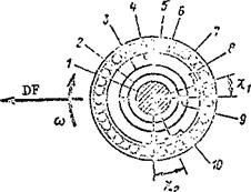
In the functional schematic (Figure 106) the longitudinal and lateral control levers are located on the fixed ring opposite the universal axes.
In the real tilt control these levers are located at some angle relative to the universal axes, which is called the control lead angle (x) • In the absence of lead the cone axis will not deflect in the direction of cyclic control stick deflection, rather at some angle ahead in the direction of rotor rotation. This lag in the deflection of the cone-of—revolution axis is associated with the inertia of the blades.
At the 180° azimuth the pitch is minimal, but the blade flapping angle will not be minimal, since the blades will continue to flap down by inertia.
This means that the cone-of—revolution axis tilts in the direction of the 210° azimuth rather than in the direction of the 180° azimuth, i. e., the deflection of the cone-of-revolution axis will not coincide with the stick deflection, and this makes control of the helicopter more difficult. Therefore, the tilt control ring is deflected with a lead angle x = 25 – 30°, which then leads to coincidence of the deflection of the stick and the main rotor cone-of-revolution axis.
Figure 106. Main rotor control lead:
 1 – main rotor shaft; 2 – slider;
3 – universal ring; 4 – universal lateral axis; 5 – tilt control fixed ring; 6 – bearing balls; 7 – tilt control movable ring; 8 – longitudinal control lever; 9 – universal longitudinal axis; 10 – lateral control lever;
X-l ~ longitudinal control lead angle;
^2 ~ lateral control lead angle.


