Source Flow: Our Second Elementary Flow
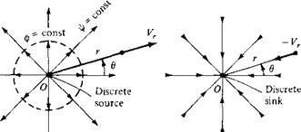
Consider a two-dimensional, incompressible flow where all the streamlines are straight lines emanating from a central point O, as shown at the left of Figure 3.20. Moreover, let the velocity along each of the streamlines vary inversely with distance from point O. Such a flow is called a source flow. Examining Figure 3.20, we see that the velocity components in the radial and tangential directions are Vr and Vg, respectively, where Vg = 0. The coordinate system in Figure 3.20 is a cylindrical
|
|
||
|

coordinate system, with the г axis perpendicular to the page. (Note that polar coordinates are simply the cylindrical coordinates r and в confined to a single plane given by г = constant.) It is easily shown (see Problem 3.9) that (1) source flow is a physically possible incompressible flow, that is, V • V = 0, at every point except the origin, where V • V becomes infinite, and (2) source flow is irrotational at every point.
In a source flow, the streamlines are directed away from the origin, as shown at the left of Figure 3.20. The opposite case is that of a sink flow, where by definition the streamlines are directed toward the origin, as shown at the right of Figure 3.20. For sink flow, the streamlines are still radial lines from a common origin, along which the flow velocity varies inversely with distance from point О. Indeed, a sink flow is simply a negative source flow.
The flows in Figure 3.20 have an alternate, somewhat philosophical interpretation. Consider the origin, point О, as a discrete source or sink. Moreover, interpret the radial flow surrounding the origin as simply being induced by the presence of the discrete source or sink at the origin (much like a magnetic field is induced in the space surrounding a current-carrying wire). Recall that, for a source flow, V • V = 0 everywhere except at the origin, where it is infinite. Thus, the origin is a singular point, and we can interpret this singular point as a discrete source or sink of a given strength, with a corresponding induced flow field about the point. This interpretation is very convenient and is used frequently. Other types of singularities, such as doublets and vortices, are introduced in subsequent sections. Indeed, the irrotational, incompressible flow field about an arbitrary body can be visualized as a flow induced by a proper distribution of such singularities over the surface of the body. This concept is fundamental to many theoretical solutions of incompressible flow over airfoils and other aerodynamic shapes, and it is the very heart of modem numerical techniques for the solution of such flows. You will obtain a greater appreciation for the concept of distributed singularities for the solution of incompressible flow in Chapters 4 through
6. At this stage, however, simply visualize a discrete source (or sink) as a singularity that induces the flows shown in Figure 3.20.
Let us look more closely at the velocity field induced by a source or sink. By definition, the velocity is inversely proportional to the radial distance r. As stated earlier, this velocity variation is a physically possible flow, because it yields V • V =
0. Moreover, it is the only such velocity variation for which the relation V • V = 0 is satisfied for the radial flows shown in Figure 3.20. Hence,
Vr = – [3.59a]
r
and Ve = 0 [3.59b]
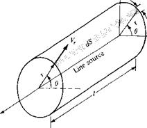
where c is constant. The value of the constant is related to the volume flow from the source, as follows. In Figure 3.20, consider a depth of length l perpendicular to the page, that is, a length l along the z axis. This is sketched in three-dimensional perspective in Figure 3.21. In Figure 3.21, we can visualize an entire line of sources along the z axis, of which the source О is just part. Therefore, in a two-dimensional flow, the discrete source, sketched in Figure 3.20, is simply a single point on the line source shown in Figure 3.21. The two-dimensional flow shown in Figure 3.20 is the
|
|
|
|
|
|
|
|
|

same in any plane perpendicular to the z, axis, that is, for any plane given by z, = constant. Consider the mass flow across the surface of the cylinder of radius r and height l as shown in Figure 3.21. The elemental mass flow across the surface element dS shown in Figure 3.21 is pV • dS = pVr( r d6){l). Hence, noting that Vr is the same value at any в location for the fixed radius r, the total mass flow across the surface of the cylinder is
![]() [3.60]
[3.60]
Since p is defined as the mass per unit volume and m is mass per second, then m/p is the volume flow per second. Denote this rate of volume flow by v. Thus, from Equation (3.60), we have
![]() m
m
v = — = 2nrlVr P
Moreover, the rate of volume flow per unit length along the cylinder is Ь/1. Denote this volume flow rate per unit length (which is the same as per unit depth perpendicular to the page in Figure 3.20) as Л. Hence, from Equation 3.61, we obtain
Hence, comparing Equations (3.59a) and (3.62), we see that the constant in Equation (3.59a)isc = А/2л. In Equation (3.62), Л defines the source length: it is physically the rate of volume flow from the source, per unit depth perpendicular to the page
of Figure 3.20. Typical units of Л are square meters per second or square feet per second. In Equation (3.62), a positive value of Л represents a source, whereas a negative value represents a sink.
The velocity potential for a source can be obtained as follows. From Equations
(2.157) , (3.5%), and (3.62),
|
Э Ф A — = Vr =———- dr 2nr |
[3.63] |
|
1 Э ф and ——————————————— = Ve = 0 г дв |
[3.64] |
|
Integrating Equation (3.63) with respect to r, we have |
|
|
Ф = ^Inr + f(6) L7Z |
[3.65] |
|
Integrating Equation (3.64) with respect to в, we have |
|
|
ф = const + f{r) |
[3.66] |
Comparing Equations (3.65) and (3.66), we see that fir) = (h/2n) In r and f(6) = constant. As explained in Section 3.9, the constant can be dropped without loss of rigor, and hence Equation (3.65) yields
Equation (3.67) is the velocity potential for a two-dimensional source flow.
The stream function can be obtained as follows. From Equations (2.151a and b), (3.59b), and (3.62),
Integrating Equation (3.68) with respect to в, we obtain
ф = ^в + f(r) [3.70]
in
Integrating Equation (3.69) with respect to r, we have
ф = const + f(6) [3.71]
Comparing Equations (3.70) and (3.71) and dropping the constant, we obtain
![]() [3.72]
[3.72]
Equation (3.72) is the stream function for a two-dimensional source flow.
The equation of the streamlines can be obtained by setting Equation (3.72) equal to a constant:
Л
f — —в = const [3.73]
2tt
From Equation (3.73), we see that в — constant, which, in polar coordinates, is the equation of a straight line from the origin. Hence, Equation (3.73) is consistent with the picture of the source flow sketched in Figure 3.20. Moreover, Equation (3.67) gives an equipotential line as r = constant, that is, a circle with its center at the origin, as shown by the dashed line in Figure 3.20. Once again, we see that streamlines and equipotential lines are mutually perpendicular.
To evaluate the circulation for source flow, recall the V x V = 0 everywhere. In turn, from Equation (2.137),
Г = ~ JJ(V x V) – dS = 0
5
for any closed curve C chosen in the flow field. Hence, as in the case of uniform flow discussed in Section 3.9, there is no circulation associated with the source flow.
It is straightforward to show that Equations (3.67) and (3.72) satisfy Laplace’s equation, simply by substitution into V20 = 0 and V2i/r = 0 written in terms of cylindrical coordinates [see Equation (3.42)]. Therefore, source flow is a viable elementary flow for use in building more complex flows.


