Specification of the Flow Field
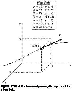
In Section 2.2.3 we defined both scalar and vector fields. We now apply this concept of a field more directly to an aerodynamic flow. One of the most straightforward ways of describing the details of an aerodynamic flow is simply to visualize the flow in three-dimensional space, and to write the variation of the aerodynamic properties as a function of space and time. For example, in cartesian coordinates the equations
P = p(x, y, z, t) [2.33a]
p = p(x, y,z, t) [2.33b]
T = T(x, y, z, t) [2.33c]
and V = ui + vj + iuk [2.34a]
where и = u(x, y,z, t) [2.34b]
v = v(x, y,z, t) [2.34c]
w = w(x, y,z, t) [2.34<f]
represent the flow field. Equations (2.33a-c) give the variation of the scalar flow field variables pressure, density, and temperature, respectively. (In equilibrium thermodynamics, the specification of two state variables, such as p and p, uniquely defines the values of all other state variables, such as T. In this case, one of Equations (2.33) can be considered redundant.) Equations (ІЗАа-d) give the variation of the vector flow field variable velocity V, where the scalar components of V in the x, y. and г directions are u, v, and w, respectively.
Figure 2.14 illustrates a given fluid element moving in a flow field specified by Equations (2.33) and (2.34). At the time t, the fluid element is at point 1, located at (xi, yi, zi) as shown in Figure 2.14.
At this instant, its velocity is V i and its pressure is given by
p = p(xi, y,z,t)
and similarly for its other flow variables.
By definition, an unsteady flow is one where the flow field variables at any given point are changing with time. For example, if you lock your eyes on point 1 in
Figure 2.14, and keep them fixed on point 1, if the flow is unsteady you will observe p, p, etc. fluctuating with time. Equations (2.33) and (2.34) describe an unsteady flow field because time t is included as one of the independent variables. In contrast, a steady flow is one where the flow field variables at any given point are invariant with time, that is, if you lock your eyes on point 1 you will continuously observe the same constant values for p, p, V etc. for all time. A steady flow field is specified by the relations
p = p(x, y,z) p = p(x, y,z) etc.
The concept of the flow field, and a specified fluid element moving through it as illustrated in Figure 2.14, will be revisited in Section 2.9 where we define and discuss the concept of the substantial derivative.
![]()
 |
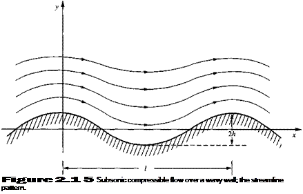
The subsonic compressible flow over a cosine-shaped (wavy) wall is illustrated in Figure 2.15. The wavelength and amplitude of the wall are l and h, respectively, as shown in Figure 2.15. The streamlines exhibit the same qualitative shape as the wall, but with diminishing amplitude as distance above the wall increases. Finally, as у —у oo, the streamline becomes straight. Along this straight streamline, the freestream velocity and Mach number are and M^,
 |
Streamline at <»
respectively. The velocity field in cartesian coordinates is given by
where p = У1 —
Consider the particular flow that exists for the case where і = 1.0 m, h = 0.01 m, = 240 m/s, and = 0.7. Also, consider a fluid element of fixed mass moving along a streamline in the flow field. The fluid element passes through the point (x/i, y/t) = (J, 1). At this point, calculate the time rate of change of the volume of the fluid element, per unit volume.
Solution
From Section 2.3.4, we know that the time rate of change of the volume of a moving fluid element of fixed mass, per unit volume, is given by the divergence of the velocity V • V. In
12,411
Equation (2.41) gives the time rate of change of the volume of the fluid element, per unit volume, as it passes through the point (x/i, у ft) = (j, 1). Note that it is a finite (nonzero) value; the volume of the fluid element is changing as it moves along the streamline. This is consistent with the definition of a compressible flow, where the density is a variable and hence the volume of a fixed mass must also be variable. Note from Equation (2.40) that V • V = 0 only along vertical lines denoted by x/l = 0, j, 1, 1 ^,…, where the sin(2jrx/£) goes to zero. This is a peculiarity associated with the cyclical nature of the flow field over the cosine-shaped wall. For the particular flow considered here, where і = 1.0 m, h = 0.01 m, Vx = 240 m/s, and Мы = 0.7, where
P = 7l – Ml = Vl – (0.7)2 = 0.714
Equation (2.41) yields
 V • V = ^0.714 – (240)(0.01) e-2*<0’714) =
The physical significance of this result is that, as the fluid element is passing through the point (f, 1) in the flow, it is experiencing a 73 percent rate of decrease of volume per second (the negative quantity denotes a decrease in volume). That is, the density of the fluid element is increasing. Hence, the point (і, 1) is in a compression region of the flow, where the fluid element will experience a decrease in density. Expansion regions are defined by values of x 11 which yield negative values of the sine function in Equation (2.40), which in turn yields a positive value for V • V, which gives an increase in volume of the fluid element, hence a decrease in density. Clearly, as the fluid element continues its path through this flow field, it experiences cyclical increases and decreases in density, as well as the other flow field properties.


