Supersonic flow over an aerofoil
We are now in a position to look at the supersonic flow over an aerofoil – but what is to be the shape of our supersonic aerofoil?
Since straight lines and sharp corners seem to be at least as good as curves, the simplest aerofoil section for supersonic speeds would seem to be a flat plate inclined at a small angle of attack, and there is no doubt that if it were possible to give adequate strength to such a plate it would be the obvious answer.
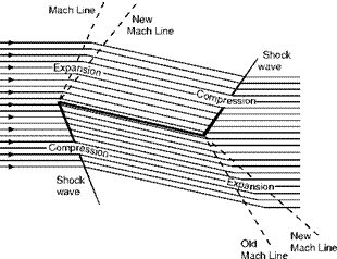
If the plate were thin enough the flow would be undisturbed at zero angle of attack – and of course there would be no lift. At a small angle, on the top surface there would be an expansion wave at the leading edge and a shock wave at the trailing edge, and on the bottom surface a shock wave at the leading edge and an expansion wave at the trailing edge, the flow being as in Fig. 12.8.
On the top surface, owing to the expansion wave at the leading edge, the flow would be speeded up and there would be a decreased pressure; on the bottom surface, owing to the shock wave at the leading edge, the flow would be slowed down, and there would be an increased pressure. So there would be lift – and drag.
But a flat plate is clearly not a practical proposition, so let us have a look at a shape that is – the double-wedge.
First let us see what happens at zero angle of attack (Fig. 12.9, overleaf).
 |
|
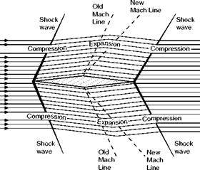
The pattern of shock waves and expansions will, of course, be the same on both top and bottom surfaces. At the nose (which corresponds exactly to the small-angled wedge of Fig. 12.4) there will be shock waves, and the consequent increases in pressure, density, and temperature, and a decrease in
|

Fig 12.9 Supersonic flow over double-wedge at zero angle of attack velocity; at the point of maximum camber there will be the expansions, and the corresponding changes over the rear portion of the aerofoil; at the trailing edge, though not perhaps quite so obvious, there will again be the wedge effect, shock waves on both surfaces, and again the changes of pressure, density, temperature, and velocity.
At very small angles of attack, for reasons that should now be quite clear, the bow shock wave on the upper surface becomes less intense and that on the lower surface more intense; the tail shock wave, on the other hand, becomes more intense on the upper surface and less intense on the lower surface. But one of the most interesting, and perhaps surprising, features of the flow is that there is no upwash in front of the aerofoil (how can there be when the airflow doesn’t know that the aerofoil is coming?) – and no down wash behind the aerofoil; the deflection of the air is only between the shock waves. The pressure distribution over the aerofoil accounts for both lift and drag – as it did with the flat plate, which also caused neither upwash nor downwash. After all, a speedboat travelling through the water causes a considerable depression (and rising) of the water as it passes, but it does not leave a permanent dent!
When the angle of attack reaches that at which the front portion of the top surface is parallel to the approaching airflow (an important condition because it gives the maximum lift/drag ratio for this type of aerofoil) the bow shock wave on the upper surface, and the tail shock wave on the lower surface, both disappear – as one would expect (Fig. 12.10).
At a still larger angle – but the reader may like to draw this for himself. Eventually, as the angle of attack is increased, the bow wave will become detached, as it always is in front of a blunt nose.
The reader should have no difficulty in sketching the flow patterns for other shapes (such as those in Figs 12.20, 12.21, and 12.22), and at various angles.


