The Kutta Condition
The lifting flow over a circular cylinder was discussed in Section 3.15, where we observed that an infinite number of potential flow solutions were possible, corresponding to the infinite choice of Г. For example, Figure 3.28 illustrates three different flows over the cylinder, corresponding to three different values of Г. The same situation applies to the potential flow over an airfoil; for a given airfoil at a given angle of attack, there are an infinite number of valid theoretical solutions, corresponding to an
3 It is interesting to note that some recent research by NASA is hinting that even as complex a problem as flow separation, heretofore thought to be a completely viscous-dominated phenomenon, may in reality be an inviscid-dominated flow which requires only a rotational flow. For example, some inviscid flow-field numerical solutions for flow over a circular cylinder, when vorticity is introduced either by means of a nonuniform freestream or a curved shock wave, are accurately predicting the separated flow on the rearward side of the cylinder. However, as exciting as these results may be, they are too preliminary to be emphasized in this book. We continue to talk about flow separation in Chapters 15 to 20 as being a viscous-dominated effect, until definitely proved otherwise. This recent research is mentioned here only as another example of the physical connection between vorticity, vortex sheets, viscosity, and real life.
infinite choice of Г. For example, Figure 4.12 illustrates two different flows over the same airfoil at the same angle of attack but with different values of Г. At first, this may seem to pose a dilemma. We know from experience that a given airfoil at a given angle of attack produces a single value of lift (e. g., see Figure 4.5). So, although there is an infinite number of possible potential flow solutions, nature knows how to pick a particular solution. Clearly, the philosophy discussed in the previous section is not complete—we need an additional condition that fixes Г for a given airfoil at a given a.
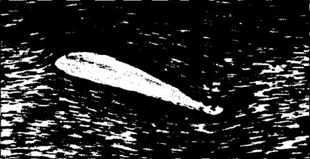
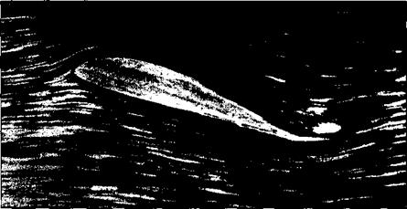
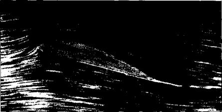
To attempt to find this condition, let us examine some experimental results for the development of the flow field around an airfoil which is set into motion from an initial state of rest. Figure 4.13 shows a series of classic photographs of the flow over an airfoil, taken from Prandtl and Tietjens (Reference 8). In Figure 4.13a, the flow has just started, and the flow pattern is just beginning to develop around the airfoil. In these early moments of development, the flow tries to curl around the sharp trailing edge from the bottom surface to the top surface, similar to the sketch shown at the left of Figure 4.12. However, more advanced considerations of inviscid, incompressible flow (see, e. g., Reference 9) show the theoretical result that the velocity becomes infinitely large at a sharp comer. Hence, the type of flow sketched at the left of Figure 4.12, and shown in Figure 4.13a, is not tolerated very long by nature. Rather, as the real flow develops over the airfoil, the stagnation point on the upper surface (point 2 in Figure 4.12) moves toward the trailing edge. Figure 4.13b shows this intermediate stage. Finally, after the initial transient process dies out, the steady flow shown in Figure 4.13c is reached. This photograph demonstrates that the flow is smoothly leaving the top and the bottom surfaces of the airfoil at the trailing edge. This flow pattern is sketched at the right of Figure 4.12 and represents the type of pattern to be expected for the steady flow over an airfoil.
Reflecting on Figures 4.12 and 4.13, we emphasize again that in establishing the steady flow over a given airfoil at a given angle of attack, nature adopts that particular value of circulation (Г2 in Figure 4.12) which results in the flow leaving smoothly at the trailing edge. This observation was first made and used in a theoretical analysis by the German mathematician M. Wilhelm Kutta in 1902. Therefore, it has become known as the Kutta condition.
|
Figure 4.12 Effect of different values of circulation on the potential flow over a given airfoil at a given angle of attack. Points 1 and 2 are stagnation points. |
|
(a) |
|
(b) Figure 4.1 3 The development of steady flow over an airfoil; the airfoil is impulsively started from rest and attains a steady velocity through the fluid, (a) A moment just after starting, (b) An intermediate time. (Source: Prandtl and Tiejens, Reference 8.) |
In order to apply the Kutta condition in a theoretical analysis, we need to be more precise about the nature of the flow at the trailing edge. The trailing edge can have a finite angle, as shown in Figures 4.12 and 4.13 and as sketched at the left of Figure 4.14, or it can be cusped, as shown at the right of Figure 4.14. First, consider the trailing edge with a finite angle, as shown at the left of Figure 4.14. Denote the velocities along the top surface and the bottom surface as V and to, respectively. Vt
|
|
|
is parallel to the top surface at point a, and V2 is parallel to the bottom surface at point a. For the finite-angle trailing edge, if these velocities were finite at point a, then we would have two velocities in two different directions at the same point, as shown at the left of Figure 4.14. Flowever, this is not physically possible, and the only recourse is for both Vj and V2 to be zero at point a. That is, for the finite trailing edge, point a is a stagnation point, where Vj = V2 = 0. In contrast, for the cusped trailing edge shown at the right of Figure 4.14, V and V2 are in the same direction at point a, and hence both Vj and V2 can be finite. Flowever, the pressure at point a, p2, is a single, unique value, and Bernoulli’s equation applied at both the top and bottom surfaces immediately adjacent to point a yields
Pa + pV i2 = Pa + pV2
![]() Vj = F2
Vj = F2
Hence, for the cusped trailing edge, we see that the velocities leaving the top and bottom surfaces of the airfoil at the trailing edge are finite and equal in magnitude and direction.
We can summarize the statement of the Kutta condition as follows:
1. For a given airfoil at a given angle of attack, the value of Г around the airfoil is such that the flow leaves the trailing edge smoothly.
2. If the trailing-edge angle is finite, then the trailing edge is a stagnation point.
3. If the trailing edge is cusped, then the velocities leaving the top and bottom surfaces at the trailing edge are finite and equal in magnitude and direction.
Consider again the philosophy of simulating the airfoil with vortex sheets placed either on the surface or on the camber line, as discussed in Section 4.4. The strength of such a vortex sheet is variable along the sheet and is denoted by у (і). The statement of the Kutta condition in terms of the vortex sheet is as follows. At the trailing edge (ТЕ), from Equation (4.8), we have
У (ТЕ) = y(a) = V1- V2 [4.9]
However, for the finite-angle trailing edge, V = V2 = 0; hence, from Equation (4.9), у (ТЕ) = 0. For the cusped trailing edge, V = V2 Ф 0; hence, from Equation (4.9), we again obtain the result that у (ТЕ) = 0. Therefore, the Kutta condition expressed in terms of the strength of the vortex sheet is
[4.10]


