The Lifting-Surface Theory and the Vortex Lattice Numerical Method
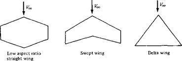
Prandtl’s classical lifting-line theory (Section 5.3) gives reasonable results for straight wings at moderate to high aspect ratio. However, for low-aspect-ratio straight wings, swept wings, and delta wings, classical lifting-line theory is inappropriate. For such planforms, sketched in Figure 5.30, a more sophisticated model must be used. The purpose of this section is to introduce such a model and to discuss its numerical implementation. However, it is beyond the scope of this book to elaborate on the details of such higher-order models; rather, only the flavor is given here. You are encouraged to pursue this subject by reading the literature and by taking more advanced studies in aerodynamics.
Return to Figure 5.13. Here, a simple lifting line spans the wing, with its associated trailing vortices. The circulation Г varies with у along the lifting line. Let us extend this model by placing a series of lifting lines on the plane of the wing, at different chordwise stations; that is, consider a large number of lifting lines all parallel to the у axis, located at different values of jc, as shown in Figure 5.31. In the limit of an infinite number of lines of infinitesimal strength, we obtain a vortex sheet, where the vortex lines run parallel to the у axis. The strength of this sheet (per unit length in the л direction) is denoted by у, where у varies in the >• direction, analogous to the variation of Г for the single lifting line in Figure 5.13. Moreover, each lifting line will have, in general, a different overall strength, so that у varies with x also. Hence, у = y(x, v) as shown in Figure 5.31. In addition, recall that each lifting line has a system of trailing vortices; hence, the series of lifting lines is crossed
![]()
|
|
|
|
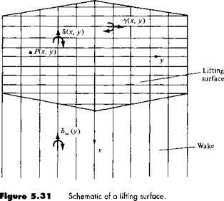
by a series of superimposed trailing vortices parallel to the x axis. In the limit of an infinite number of infinitesimally weak vortices, these trailing vortices form another vortex sheet of strength S (per unit length in the у direction). [Note that this S is different from the S used in Equation (5.61); the use of the same symbol in both cases is standard, and there should be no confusion since the meanings and context are completely different.] To see this more clearly, consider a single line parallel to the x axis. As we move along this line from the leading edge to the trailing edge, we pick up an additional superimposed trailing vortex each time we cross a lifting line. Hence,
S must vary with x. Moreover, the trailing vortices are simply parts of the horseshoe vortex systems, the leading edges of which make up the various lifting lines. Since the circulation about each lifting line varies in the у direction, the strengths of different trailing vortices will, in general, be different. Hence, & also varies in the у direction, that is, & = S(x, y), as shown in Figure 5.31. The two vortex sheets—the one with vortex lines running parallel to у with strength у (per unit length in the x direction) and the other with vortex lines running parallel to x with strength <5 (per unit length in the у direction)—result in a lifting surface distributed over the entire planform of the wing, as shown in Figure 5.31. At any given point on the surface, the strength of the lifting surface is given by both у and 8, which are functions of x and y. We denote у = y(x, у) as the spanwise vortex strength distribution and 3 = 8(x, y) as the chordwise vortex strength distribution.
Note that downstream of the trailing edge we have no spanwise vortex lines, only trailing vortices. Hence, the wake consists of only chordwise vortices. The strength of this wake vortex sheet is given by 8W (per unit length in the у direction). Since in the wake the trailing vortices do not cross any vortex lines, the strength of any given trailing vortex is constant with x. Hence, <$„, depends only on у and, throughout the wake, 8w(y) is equal to its value at the trailing edge.
Now that we have defined the lifting surface, of what use is it? Consider point P located at (x, y) on the wing, as shown in Figure 5.31. The lifting surface and the wake vortex sheet both induce a normal component of velocity at point P. Denote this normal velocity by w(x, y). We want the wing planform to be a stream surface of the flow; that is, we want the sum of the induced w{x, y) and the normal component of the freestream velocity to be zero at point P and for all points on the wing—this is the flow-tangency condition on the wing surface. (Keep in mind that we are treating the wing as a flat surface in this discussion.) The central theme of lifting-surface theory is to find у (x, y) and <$(x, y) such that the flow-tangency condition is satisfied at all points on the wing. [Recall that in the wake, <$„,(>•) is fixed by the trailing – edge values of 8(x, y); hence, 8w(y) is not, strictly speaking, one of the unknown dependent variables.!
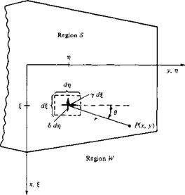
Let us obtain an expression for the induced normal velocity w(x, y) in terms of y, S, and Sw. Consider the sketch given in Figure 5.32, which shows a portion of the planview of a finite wing. Consider the point given by the coordinates (£, t]). At this point, the spanwise vortex strength is rj). Consider a thin ribbon, or filament, of the spanwise vortex sheet of incremental length d£ in the x direction. Hence, the strength of this filament is у d^, and the filament stretches in the у (or rj) direction. Also, consider point P located at (x, y) and removed a distance r from the point (§, rj). From the Biot-Savart law, Equation (5.5), the incremental velocity induced at P by a segment drj of this vortex filament of strength у d£ is
Examining Figure 5.32, and following the right-hand rule for the strength y, note that |dV| is induced downward, into the plane of the wing (i. e., in the negative z direction). Following the usual sign convention that w is positive in the upward direction (i. e., in
|
the positive z direction), we denote the contribution of Equation (5.77) to the induced velocity w as (dw)y = — |dV|. Also, note that sin в = (x — §)/r. Hence, Equation (5.77) becomes
Considering the contribution of the elemental chordwise vortex of strength S dri to the induced velocity at P, we find by an analogous argument that
To obtain the velocity induced at P by the entire lifting surface, Equations (5.78) and
(4.79) must be integrated over the wing planform, designated as region S in Figure
5.32. Moreover, the velocity induced at P by the complete wake is given by an equation analogous to Equation (5.79), but with Sw instead of S, and integrated over the wake, designated as region W in Figure 5.32. Noting that
r = s/(x -£)2 + (y – r])2
the normal velocity induced at P by both the lifting surface and the wake is
The central problem of lifting-surface theory is to solve Equation (5.80) for y(£, rf) and 5(£, T]) such that the sum of w(x, y) and the normal component of the freestream is zero, that is, such that the flow is tangent to the planform surface S. The details of various lifting-surface solutions are beyond the scope of this book; rather, our purpose here was simply to present the flavor of the basic model.
The advent of the high-speed digital computer has made possible the implementation of numerical solutions based on the lifting-surface concept. These solutions are similar to the panel solutions for two-dimensional flow discussed in Chapters 3 and 4 in that the wing planform is divided into a number of panels, or elements. On each panel, either constant or prescribed variations of both у and S can be made. Control points on the panels can be chosen, where the net normal flow velocity is zero. The evaluation of equations like Equation (5.80) at these control points results in a system of simultaneous algebraic equations that can be solved for the values of the y’s and 5’s on all the panels.
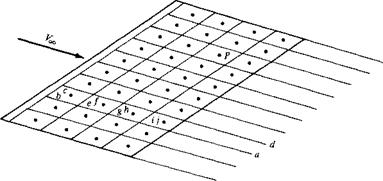
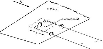
A related but somewhat simpler approach is to superimpose a finite number of horseshoe vortices of different strengths F„ on the wing surface. For example, consider Figure 5.33, which shows part of a finite wing. The dashed lines define a panel on the wing planform, where l is the length of the panel in the flow direction. The panel is a trapezoid; it does not have to be a square, or even a rectangle. A horseshoe vortex abed of strength Г,, is placed on the panel such that the segment be is a distance 1/4 from the front of the panel. A control point is placed on the
|
|
|
|
|
|
centerline of the panel at a distance | / from the front. The velocity induced at an arbitrary point P only by the single horseshoe vortex can be calculated from the Biot-Savart law by treating each of the vortex filaments ab, be, and cd separately. Now consider the entire wing covered by a finite number of panels, as sketched in Figure 5.34. A series of horseshoe vortices is now superimposed. For example, on one panel at the leading edge, we have the horseshoe vortex abed. On the panel behind it, we have the horseshoe vortex aefd. On the next panel, we have aghd, and on the next, aijd, etc. The entire wing is covered by this lattice of horseshoe vortices, each of different unknown strength Г„. At any control point P, the normal velocity induced by all the horseshoe vortices can be obtained from the Biot-Savart law. When the flow-tangency condition is applied at all the control points, a system of simultaneous algebraic equations results which can be solved for the unknown r„’s. This numerical approach is called the vortex lattice method and is in wide use today for the analysis of finite-wing properties. Once again, only the flavor of the method is given above; you are encouraged to read the volumes of literature that now exist on various versions of the vortex lattice method. In particular, Reference 13 has an excellent introductory discussion on the vortex lattice method, including a worked example that clearly illustrates the salient points of the technique.
 |
|
|||
|
|||
|
|
||
|
|||
|
|||
|
|||
|
|||
|
|||
|


