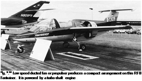
The low speed ducted fan or propulsor
The alternative flow pattern shown in Fig. 6.10 and 6.13 is obtained when the thrust is high in relation to the free-stream speed. It therefore occurs when any turbo-fan aircraft is taking off. As the aircraft speed increases, the flow pattern gradually changes to that shown in Fig. 6.12.
In Fig. 6.13, we have superimposed the surrounding stream-tube shape for a propeller producing the same thrust. It will be seen that when operated at low speed, the ducted fan is equivalent to a propeller of larger diameter. The propulsive efficiency of the ducted fan should thus be higher than for an unducted propeller of the same diameter.
In the situation illustrated in Fig. 6.13 the flow speeds up as it approaches the fan, and the pressure at inlet is thus lower than the free-stream value. This is not a disadvantage in low speed flight, where there are no problems due to compressibility effects. An example of a ducted fan installation may be seen on the Fantrainer shown in Fig. 6.14. The Optica, shown in Fig. 4.9, is another example.
 |
 Fig. 6.13 Ducted fan at low speed
 |
The surrounding stream-tube for a propeller producing the same amount of thrust is also shown. It will be seen that the ducted fan is equivalent to a propeller of larger diameter
Apart from increasing the effective diameter, the ducted fan can reduce noise, and also provide a means of containment, if one of the blades should come off; an important feature for the propulsion of airships.
Because the fan diameter is smaller than the equivalent propeller, it can be run at a higher rotational speed, which is an advantage when the drive is taken directly from the engine shaft.
To prevent flow separation, the propulsor duct intake needs to be shaped quite differently from the high speed type, as may be seen from comparison of Figs 6.12 and 6.13. The propulsor duct is rather like an annular aerofoil, and sustains a circulation. Leading-edge suction provides part of the overall thrust. The power required to produce that thrust still ultimately comes from the engine, of course.
The disadvantage of the propulsor is that it adds to the weight, cost and the complexity of the aircraft. The duct also produces some extra surface friction drag, and the overall increase in efficiency may be small.


