The Vortex Filament, the Biot-Savart Law, and Helmholtz’s Theorems
To establish a rational aerodynamic theory for a finite wing, we need to introduce a few additional aerodynamic tools. To begin with, we expand the concept of a vortex filament first introduced in Section 4.4. In Section 4.4, we discussed a straight vortex filament extending to ±oo. (Review the first paragraph of Section 4.4 before proceeding further.)
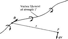
In general, a vortex filament can be curved, as shown in Figure 5.6. Here, only a portion of the filament is illustrated. The filament induces a flow field in the surrounding space. If the circulation is taken about any path enclosing the filament, a constant value Г is obtained. Hence, the strength of the vortex filament is defined as Г. Consider a directed segment of the filament dl, as shown in Figure 5.6. The radius vector from dl to an arbitrary point P in space is r. The segment dl induces a velocity at P equal to
Equation (5.5) is called the Biot-Savart law and is one of the most fundamental relations in the theory of inviscid, incompressible flow. Its derivation is given in more advanced books (see, e. g., Reference 9). Here, we must accept it without proof. However, you might feel more comfortable if we draw an analogy with electromagnetic theory. If the vortex filament in Figure 5.6 were instead visualized as a wire carrying an electrical current /, then the magnetic field strength dB induced at point P by a segment of the wire dl with the current moving in the direction of dl is
where ц, is the permeability of the medium surrounding the wire. Equation (5.6) is identical in form to Equation (5.5). Indeed, the Biot-Savart law is a general result of potential theory, and potential theory describes electromagnetic fields as well as
![]()
|
inviscid, incompressible flows. In fact, our use of the word “induced” in describing velocities generated by the presence of vortices, sources, etc. is a carry-over from the study of electromagnetic fields induced by electrical currents. When developing their finite-wing theory during the period 1911-1918, Prandtl and his colleagues even carried the electrical terminology over to the generation of drag, hence the term “induced” drag.
Return again to our picture of the vortex filament in Figure 5.6. Keep in mind that this single vortex filament and the associated Biot-Savart law [Equation (5.5)] are simply conceptual aerodynamic tools to be used for synthesizing more complex flows of an inviscid, incompressible fluid. They are, for all practical purposes, a solution of the governing equation for inviscid, incompressible flow—Laplace’s equation (see Section 3.7)—and, by themselves, are not of particular value. However, when a number of vortex filaments are used in conjunction with a uniform freestream, it is possible to synthesize a flow which has a practical application. The flow over a finite wing is one such example, as we will soon see.
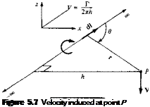
Let us apply the Biot-Savart law to a straight vortex filament of infinite length, as sketched in Figure 5.7. The strength of the filament is Г. The velocity induced at point P by the directed segment of the vortex filament dl is given by Equation (5.5). Hence, the velocity induced at P by the entire vortex filament is
 [5.7]
[5.7]
From the definition of the vector cross product (see Section 2.2), the direction of V
![]() [5.8]
[5.8]
 |
In Figure 5.7, let h be the perpendicular distance from point P to the vortex filament.
by an infinite, straight vortex filament.
Then, from the geometry shown in Figure 5.7,
Substituting Equations (5.9a to c) in Equation (5.8), we have
Thus, the velocity induced at a given point P by an infinite, straight vortex filament at a perpendicular distance h from P is simply Г/2лІг, which is precisely the result given by Equation (3.105) for a point vortex in two-dimensional flow. [Note that the minus sign in Equation (3.105) does not appear in Equation (5.10); this is because V in Equation (5.10) is simply the absolute magnitude of V, and hence it is positive by definition.]
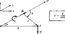
Consider the semi-infinite vortex filament shown in Figure 5.8. The filament extends from point A to oo. Point A can be considered a boundary of the flow. Let P be a point in the plane through A perpendicular to the filament. Then, by an integration similar to that above (try it yourself), the velocity induced at P by the semi-infinite vortex filament is
We use Equation (5.11) in the next section.
The great German mathematician, physicist, and physician Hermann von Helmholtz (1821-1894) was the first to make use of the vortex filament concept in the analysis of inviscid, incompressible flow. In the process, he established several
![]()
|
|
|
|

|
Figure 5.0 Sketch of the lift distribution along the span of a wing. |
basic principles of vortex behavior which have become known as Helmholtz’s vortex theorems:
1. The strength of a vortex filament is constant along its length.
2. A vortex filament cannot end in a fluid; it must extend to the boundaries of the
fluid (which can be ±oo) or form a closed path.
We make use of these theorems in the following sections.
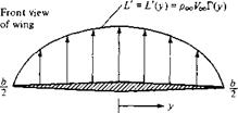
Finally, let us introduce the concept of lift distribution along the span of a finite wing. Consider a given spanwise location yb where the local chord is c, the local geometric angle of attack is a, and the airfoil section is a given shape. The lift per unit span at this location is L'(yj). Now consider another location vy along the span, where c, a, and the airfoil shape may be different. (Most finite wings have a variable chord, with the exception of a simple rectangular wing. Also, many wings are geometrically twisted so that a is different at different spanwise locations—so – called geometric twist. If the tip is at a lower a than the root, the wing is said to have washout; if the tip is at a higher a than the root, the wing has washin. In addition, the wings on a number of modern airplanes have different airfoil sections along the span, with different values of ac=o; Ibis is called aerodynamic twist.) Consequently, the lift per unit span at this different location, L'(y2), will, in general, be different from L'(y). Therefore, there is a distribution of lift per unit span along the wing, that is, L’ = L'{y), as sketched in Figure 5.9. In turn, the circulation is also a function of y, Г (у) = L'(y)/PoqVoo. Note from Figure 5.9 that the lift distribution goes to zero at the tips; that is because there is a pressure equalization from the bottom to the top of the wing precisely at у = —b/2 and b/2, and hence no lift is created at these points. The calculation of the lift distribution L(y) [or the circulation distriution Г (у)] is one of the central problems of finite-wing theory. It is addressed in the following sections.
In summary, we wish to calculate the induced drag, the total lift, and the lift distribution for a finite wing. This is the purpose of the remainder of this chapter.


