The Vortex Sheet
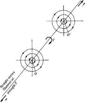
In Section 3.14, the concept of vortex flow was introduced; refer to Figure 3.31 for a schematic of the flow induced by a point vortex of strength Г located at a given point О. (Recall that Figure 3.31, with its counterclockwise flow, corresponds to a negative value of Г. By convention, a positive Г induces a clockwise flow.) Let us now expand our concept of a point vortex. Referring to Figure 3.31, imagine a straight line perpendicular to the page, going through point O, and extending to infinity both out of and into the page. This line is a straight vortex filament of strength Г. A straight vortex filament is drawn in perspective in Figure 4.7. (Here, we show a clockwise
flow, which corresponds to a positive value of Г.) The flow induced in any plane perpendicular to the straight vortex filament by the filament itself is identical to that induced by a point vortex of strength Г; that is, in Figure 4.7, the flows in the planes perpendicular to the vortex filament at О and O’ are identical to each other and are identical to the flow induced by a point vortex of strength Г. Indeed, the point vortex described in Section 3.14 is simply a section of a straight vortex filament.
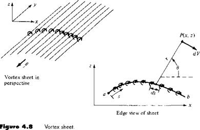
In Section 3.17, we introduced the concept of a source sheet, which is an infinite number of line sources side by side, with the strength of each line source being infinitesimally small. For vortex flow, consider an analogous situation. Imagine an infinite number of straight vortex filaments side by side, where the strength of each filament is infinitesimally small. These side-by-side vortex filaments form a vortex sheet, as shown in perspective in the upper left of Figure 4.8. If we look along the series of vortex filaments (looking along the у axis in Figure 4.8), the vortex sheet will appear as sketched at the lower right of Figure 4.8. Here, we are looking at an edge view of the sheet; the vortex filaments are all perpendicular to the page. Let і be the distance measured along the vortex sheet in the edge view. Define у = y(s) as the strength of the vortex sheet, per unit length along s. Thus, the strength of an infinitesimal portion ds of the sheet is у ds. This small section of the vortex sheet can be treated as a distinct vortex of strength у ds. Now consider point P in the flow,
|
Figure 4.7 Vortex filament. |
 |
A
located a distance r from ds; the Cartesian coordinates of P are (x, z). The small section of the vortex sheet of strength у ds induces an infinitesimally small velocity dV at point P. From Equation (3.105), dV is given by
and is in a direction perpendicular to r, as shown in Figure 4.8. The velocity at P induced by the entire vortex sheet is the summation of Equation (4.1) from point a to point b. Note that dV, which is perpendicular to r, changes direction at point P as we sum from a to b; hence, the incremental velocities induced at P by different sections of the vortex sheet must be added vectorally. Because of this, it is sometimes more convenient to deal with the velocity potential. Again referring to Figure 4.8, the increment in velocity potential d<p induced at point P by the elemental vortex у ds is, from Equation (3.112),
In turn, the velocity potential at P due to the entire vortex sheet from a to b is

![]()
![]() [4.3]
[4.3]
Equation (4.1) is particularly useful for our discussion of classical thin airfoil theory, whereas Equation (4.3) is important for the numerical vortex panel method.
Recall from Section 3.14 that the circulation Г around a point vortex is equal to the strength of the vortex. Similarly, the circulation around the vortex sheet in
Figure 4.8 is the sum of the strengths of the elemental vortices; that is
![]()
 [4.4]
[4.4]
Recall that the source sheet introduced in Section 3.17 has a discontinuous change in the direction of the normal component of velocity across the sheet (from Figure 3.38, note that the normal component of velocity changes direction by 180° in crossing the sheet), whereas the tangential component of velocity is the same immediately above and below the source sheet. In contrast, for a vortex sheet, there is a discontinuous change in the tangential component of velocity across the sheet, whereas the normal component of velocity is preserved across the sheet. This change in tangential velocity across the vortex sheet is related to the strength of the sheet as follows. Consider a vortex sheet as sketched in Figure 4.9. Consider the rectangular dashed path enclosing a section of the sheet of length ds. The velocity components tangential to the top and bottom of this rectangular path are u and иг, respectively, and the velocity components tangential to the left and right sides are r j and i>2, respectively. The top and bottom of the path are separated by the distance dn. From the definition of circulation given by Equation (2.36), the circulation around the dashed path is
Г = — (v2 dn — uds — i>i dn + иг ds)
or Г = (иі — иг) ds + (i>i — иг) dn [4.5]
However, since the strength of the vortex sheet contained inside the dashed path is у ds, we also have
Г = у ds [4.6]
Therefore, from Equations (4.5) and (4.6),
у ds = (u — иг) ds + (uj — і>г) dn [4.7]
 |
Let the top and bottom of the dashed line approach the vortex sheet; that is, let dn —»• 0. In the limit, и i and иг become the velocity components tangential to the
vortex sheet immediately above and below the sheet, respectively, and Equation (4.7) becomes
у ds = (u і — и 2 ) ds
Equation (4.8) is important; it states that the local jump in tangential velocity across the vortex sheet is equal to the local sheet strength.
We have now defined and discussed the properties of a vortex sheet. The concept of a vortex sheet is instrumental in the analysis of the low-speed characteristics of an airfoil. A philosophy of airfoil theory of inviscid, incompressible flow is as follows. Consider an airfoil of arbitrary shape and thickness in a freestream with velocity Vx, as sketched in Figure 4.10. Replace the airfoil surface with a vortex sheet of variable strength y(x), as also shown in Figure 4.10. Calculate the variation of у as a function of і such that the induced velocity field from the vortex sheet when added to the uniform velocity of magnitude Vж will make the vortex sheet (hence the airfoil surface) a streamline of the flow. In turn, the circulation around the airfoil will be given by
where the integral is taken around the complete surface of the airfoil. Finally, the resulting lift is given by the Kutta-Joukowski theorem:
L’ = Рос Too Г
This philosophy is not new. It was first espoused by Ludwig Prandtl and his colleagues at Gottingen, Germany, during the period 1912-1922. However, no general analytical solution for у = у (s) exists for an airfoil of arbitrary shape and thickness. Rather, the strength of the vortex sheet must be found numerically, and the practical implementation of the above philosophy had to wait until the 1960s with the advent of large digital computers. Today, the above philosophy is the foundation of the modern vortex panel method, to be discussed in Section 4.9.
The concept of replacing the airfoil surface in Figure 4.10 with a vortex sheet is more than just a mathematical device; it also has physical significance. In real life, there is a thin boundary layer on the surface, due to the action of friction between

 Airfoil of arbitrary shape and thickness
Figure 4.10 Simulation of an arbitrary airfoil by distributing a vortex sheet over the airfoil surface.
![]()
|
|
|
|
|
|
|
|
|

![]()
the surface and the airflow (see Figure 1.35). This boundary layer is a highly viscous region in which the large velocity gradients produce substantial vorticity; that is, V x V is finite within the boundary layer. (Review Section 2.12 for a discussion of vorticity.) Hence, in real life, there is a distribution of vorticity along the airfoil surface due to viscous effects, and our philosophy of replacing the airfoil surface with a vortex sheet (such as in Figure 4.10) can be construed as a way of modeling this effect in an inviscid flow.3
Imagine that the airfoil in Figure 4.10 is made very thin. If you were to stand back and look at such a thin airfoil from a distance, the portions of the vortex sheet on the top and bottom surface of the airfoil would almost coincide. This gives rise to a method of approximating a thin airfoil by replacing it with a single vortex sheet distributed over the camber line of the airfoil, as sketched in Figure 4.11. The strength of this vortex sheet у (s) is calculated such that, in combination with the freestream, the camber line becomes a streamline of the flow. Although the approach shown in Figure 4.11 is approximate in comparison with the case shown in Figure 4.10, it has the advantage of yielding a closed-form analytical solution. This philosophy of thin airfoil theory was first developed by Max Munk, a colleague of Prandtl, in 1922 (see Reference 12). It is discussed in Sections 4.7 and 4.8.


