THREE-DIMENSIONAL HIGHER – ORDER ELEMENTS
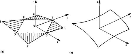
The surface shape and singularity strength distribution over an arbitrarily shaped panel can be approximated by a polynomial of a certain degree. The surface of such an arbitrary panel as shown in Fig. 10.27a can be approximated by a “zero-order” flat plane
z = a0
by a first-order surface
z = a0 + blx + b2y
by a second order surface
z = a0 + bxx 4- b2y + cxx2 + c2xy + c3y2
or any higher-order approximations. Evaluation of the influence coefficients in a closed form is possible,10 1 though, for flat surfaces and an approximation of a curved panel by five flat subpanels is shown in Fig. 10.27fi. This approach is used in the code PANAIR9 2 and for demonstrating a higher-order element let us describe this element.
For the singularity distribution a first-order source and a second-order doublet is used, and in the following paragraph the methodology is briefly described:
INFLUENCE OF SOURCE DISTRIBUTION. The source distribution on this element is approximated by a first-order polynomial:
o(x0, y0) = 0o + axx0 + <7ууо (10.121)
|
FIGURE 10.27 Approximation of a curved panel by five flat subpanels. |
where (*0, y0) are the panel local coordinates, o0, the source strength at the origin, and o0, ox and ay are three constants. The contribution of this source distribution to the potential АФ and to the induced velocity Д(и, v, w) (in the panel frame of reference) can be evaluated by performing the integral
![]()
![]()
![]() (10.122)
(10.122)
and then differentiating to get the velocity components


![]() (10.123)
(10.123)
The result of this integration depends solely on the geometry of the problem and can be evaluated for an arbitrary field point. Some details of this calculation are provided by F. T. Johnson9 2 and can be reduced to a form that depends on the panel comer point values (the comer point numbering sequence is shown in Fig. 10.27b.). Thus, in terms of these cornerpoint values the influence of the panel becomes
ДФ = Fs(<*i, o2, a3, o4, o9) =/s(0o, ax, oy) (10.124)
Д(и, v, w) = GS(01, 02, 03, oA, a9) = gs(o0, 0,, Oy) (10.125)
where the functions F, G, and /, g are linear matrix manipulations. Also, note that 0O, 04, Oy are the three basic unknowns for each panel and olt…, o9 can be evaluated based on these values (so that for each panel only three unknown values are left).
INFLUENCE OF DOUBLET DISTRIBUTION. To model the two components of vorticity on the panel surface a second-order doublet is used:
/*(*о> Уо) = Ио + ИхХ0 + ИуУо + ИххХІ + Цхух0Уо + ЦуууІ (10.126)
|
t*(xo, y0) • z dS |
|
[(* — XqF + (y — Уо)2 + z2] |
The potential due to a doublet distribution whose axis points in the г direction (see Section 3.5) is
and the induced velocity is
 . / ЭФ ЗФ ЭФ
These integrals can be evaluated (see F. Johnson9 2) in terms of the panel comer points (points 1-9, in Fig. 10.27b) and the result can be presented as
ДФ = Fd(hi, p2, ti3, цА, fis, ц6, ц7, ця, ju9)
![]() fo(.F 0, Fxf Fy> dxx, dxy, dyy)
fo(.F 0, Fxf Fy> dxx, dxy, dyy)
Д(и, v, w) = Gd(Mi, fi2, Мз, Мд, Ms, Мб, M7, Me, M9)
?d(Mo, Mj, My, M-tjc> Мдгу, Myy) (10.130)
where the functions F, G, and /, g are linear matrix manipulations, which depend on the geometry only. Also, note that fi0, цх, /лу, цхх, цху, fiyy are the five basic unknowns for each panel and цІУ . . . , /х9 can be evaluated based on these values (so that for each panel only five unknown doublet parameters are left).
For more details on higher-order elements, see Ref. 9.2.
REFERENCES
10.1. Hess, J. L., and Smith, A. M. O., “Calculation of Potential Flow About Arbitrary Bodies,” Progress in Aeronautical Sciences, vol. 8, pp. 1-138, 1967.
10.2. Browne, Lindsey E., and Ashby, Dale L., “Study of the Integration of Wind-Tunnel and Computational Methods for Aerodynamic Configurations,” NASA TM 102196, July 1989.
10.3. Sarpkaya, T., “Computational Methods With Vortices—The 1988 Freeman Scholar Lecture,” Journal of Fluids Engineering, vol. Ill, pp. 5-52, March 1989.
PROBLEMS
10.1. Find the x-component of velocity и for the constant-strength source distribution by a direct integration of Eq. (10.12).
10.2. Find the velocity potential for the constant doublet distribution by a direct integration of Eq. (10.25).
10.3. Consider the horse shoe vortex of Section 10.47, which lies in the x-y plane. For the case where the leading segment lies on the x axis (xa = 0) find the velocity induced at a point whose coordinates are x, y, and z that lies above the plane of the horse shoe.
![]()


