Trailing-Edge Angle and Beveled Controls
The included angle of upper and lower surfaces at the trailing edge, or trailing- edge angle, has a major effect on control surface aerodynamic hinge moment. This was not realized by practicing stability and control engineers until well into the World War II era. For example, a large trailing-edge angle is now known to be responsible for a puzzling rudder snaking oscillation experienced in 1937 with the Douglas DC-2 airplane. Quoting from an internal Douglas Company document of July 12, 1937 (The Museum of Flying, Santa Monica, California), by L. Eugene Root:
The first DC-2s had a very undesirable characteristic in that, even in smooth air, they would develop a directional oscillation. In rough air this characteristic was worse, and air sickness was a common complaint. …It was noticed, by watching the rudder in flight, that during the hunting the rudder moved back and forth keeping time with the oscillations of the airplane.
It is common knowledge that the control surfaces were laid out along airfoil lines. Because of this fact, the rearward portion of the vertical surface, or the rudder, had curved sides. It was thought that these curved sides were causing the trouble because of separation of the air from the surface of the rudder before reaching the trailing edge. In other words, there was a region in which the rudder could move and not hit “solid” air, thus causing the movement from side to side. The curvature was increased towards the trailing edge of the rudder in such a way as to reduce the supposedly “dead” area. . . . The change that
we made to the rudder was definitely in the wrong direction, for the airplane oscillated severely…. After trying several combinations on both elevators and rudder, we finally tried a rudder with straight sides instead of those which would normally result from the use of airfoil sections for the vertical surfaces. We were relieved when the oscillations disappeared entirely upon the use of this type of rudder.
The Douglas group had stumbled on the solution to the oscillation or snaking problem, reduction of the rudder floating tendency through reduction of the trailing-edge angle. Flatsided control surfaces have reduced trailing-edge angles compared with control surfaces that fill out the airfoil contour. We now understand the role of the control surface trailing – edge angle on hinge moments. The wing’s boundary layer is thinned on the control surface’s windward side, or the wing surface from which the control protrudes. Conversely, the wing’s boundary layer thickens on the control surface’s leeward side, where the control surface has moved away from the flow. Otherwise stated, for small downward control surface angles or positive wing angles of attack the wing’s boundary layer is thinned on the control surface bottom and thickened on the control’s upper surface.
The effect of this differential boundary layer action for down-control angles or positive wing angles of attack is to cause the flow to adhere more closely to the lower control surface side than to the upper side. In following the lower surface contour the flow curves toward the trailing edge. This curve creates local suction, just as an upward-deflected tab would do. On the other hand, the relatively thickened upper surface boundary layer causes the flow to ignore the upper surface curvature. The absence of a flow curve around the upper surface completes the analogy to the effect of an upward-deflected tab. The technical jargon for this effect is that large control surface trailing-edge angles create positive values of the derivatives Cha and Chs, the floating and restoring derivatives, respectively.
The dynamic mechanism for unstable lateral-directional oscillations with a free rudder became known on both sides of the Atlantic a little after the Douglas DC-2 experience. Unstable yaw oscillations were calculated in Britain for a rudder that floated into the wind (Bryant and Gandy, 1939). This was confirmed in two NACA studies (Jones and Cohen, 1941; Greenberg and Sternfield, 1943). The aerodynamic connection between trailing-edge angle and control surface hinge moment, including the floating tendency, completed the story (Jones and Ames, 1942).
Following the success of the flat-sided rudder in correcting yaw snaking oscillations on the Douglas DC-2, flat-sided control surfaces became standard design practice on Douglas airplanes. William H. Cook credits George S. Schairer with introducing flat-sided control surfaces at Boeing, where they were used first on the B-17E and B-29 airplanes. Trailing – edge angles of fabric-covered control surfaces vary in flight with the pressure differential across the fabric (Mathews, 1944). A Douglas C-74 transport was lost in 1946 when elevator fabric bulging between ribs increased the trailing-edge angle, causing pitch oscillations that broke off the wing tips. C-74 elevators were metal-covered after that.
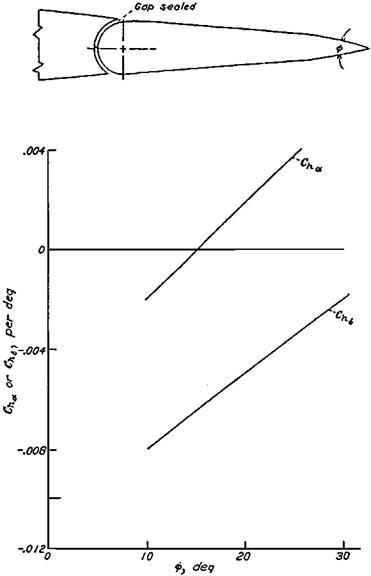
Understanding of the role of the trailing-edge angle in aerodynamic hinge moments opened the way for its use as another method of control force management. Beveled control surfaces, in which the trailing-edge angle is made arbitrarily large, is such an application (Figure 5.8). Beveled control surfaces, a British invention of World War II vintage, work like balancing tabs for small control surface angles.
The beveled-edge control works quite well for moderate bevel angles. As applied to the North American P-51 Mustang, beveled ailerons almost doubled the available rate of roll at high airspeeds, where high control forces limit the available amount of aileron deflection.
|
Figure 5.8 Typical hinge moment parametervariation with bevel angle ф for a beveled control surface. (From Phillips, NACA Rept. 927, 1948) |
But large bevel angles, around 30 degrees, acted too well at high Mach numbers, causing overbalance and unacceptable limit cycle oscillations (Figure 5.9). Beveled controls have survived into recent times, used for example on the ailerons of the Grumman/Gulfstream AA-5 Tiger and on some Mooney airplanes.


