Airfoils for Wind Turbines
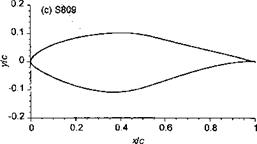
The importance of airfoil sections for any type of rotating wing cannot be underestimated, to the point that Chapter 7 has been devoted to an understanding of the subject. As has been done for helicopter rotors, entire families of airfoil sections have been developed for wind turbines. Many commercial wind turbines use standard NACA airfoil sections such as the NACA 4-digit series. In particular, the NASA LS-1 (low-speed) airfoil seems a common choice because of its known insensitivity to surface finish. Figure 13.18 shows some representative airfoils that have been used for wind turbines. The influence of airfoil
|
|
|
Figure 13.18 Examples of airfoil sections used for wind turbines: (a) NACA 4415. (b) LS(1)-0417. (c) NREL S809. |
section on the power output of a wind turbine is relatively small, but the use of an efficient low drag airfoil will always help maximize energy production. A catalog of airfoil sections for wind turbine applications has been compiled by Miley (1982). See Tangier (1987,1995) for more recent wind turbine airfoil section developments.
There are, however, some special considerations in the design, selection, and modeling of the characteristics of airfoil sections for wind turbines compared to those for a helicopter. The most important is that wind turbines operate at much lower Reynolds numbers than helicopters, typically at or below 106 even at the blade tip. This means that Reynolds number sensitivity is a more important issue and the accurate modeling of Reynolds number effects on the aerodynamic characteristics of the blade will be critical if the blade loads and power output from the wind turbine are to be predicted accurately. Again, these effects are readily implemented using look-up table techniques or equations fitted to the measured airfoil characteristics (Section 7.11.3). As previously mentioned, also important is a knowledge of the sensitivity of the airfoils to surface roughness. The normal operation of wind turbines in the low atmosphere tends to cause the accumulation of dirt and dead insects and other foreign matter at the leading edge of the blades, and this can act to degrade airfoil performance and reduce turbine power output – see Clark & Davis (1991) and Eggleston (1991). Representative effects of surface roughness on airfoil performance have been shown previously in Fig. 7.37 and appear as increased drag, decreased maximum lift and perhaps as a change in stall characteristic, usually leading to a very gradual or “soft” stall.
For variable blade pitch (feathering) turbines, airfoil sections are designed for high values of maximum lift, in much the same way as is done for helicopters – see Section 7.9. The pitch control system is used to adjust the AoA so that the best energy extraction efficiency is obtained over a wide range of wind speeds up to maximum power. For fixed pitch stall, controlled wind turbines, the airfoil sections must be designed to begin stall at lower values
 |
Angle of attack – deg.
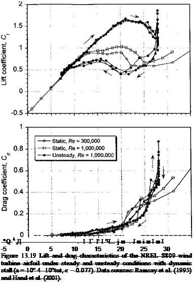
of lift coefficient and then to maintain that value over a relatively wide range of angles of attack. This requires airfoil sections with appropriate pressure distributions that initially promote trailing edge separation and thus make this prestall behavior relatively insensitive to AoA. One example is the NREL S809 airfoil [see Tangier (1987)], the geometric shape of which is shown in Fig. 13.18(c) and the aerodynamic characteristics are given in Fig. 13.19. Notice that under steady (static) conditions the maximum lift is obtained at a moderate angle of attack, the lift then plateaus for about an 8 degree AoA range as trailing edge separation develops and stabilizes. This helps regulate the turbine’s power output. Over this range there is only a modest increase in the sectional drag. Gross breakdown of the flow and static stall occurs at about 15°. These characteristics are also carried forward somewhat into the dynamic regime, with lift overshoots but with relatively wide flat lift peaks compared to those found on helicopter airfoil sections under dynamic stall conditions (see, for example, Fig. 9.15). In this case, the lift overshoots are a result of the suppression of trailing edge
flow separation and not the formation of dynamic stall per se, and “classic” dynamic stall with leading edge vortex shedding is not obtained until a much higher AoA.


