Blade Element Momentum Theory for a Wind Turbine
The blade element momentum theory (BEMT) is a hybrid method that exploits the fundamental equivalence between the circulation and momentum theories of lift. With certain assumptions, the BEMT allows the induction factor along the blade to be estimated. Thereafter, all the other airloads can be determined. The BEMT allows a clear examination of the principal design factors that influence wind turbine performance and design. How-
pvp. r the. RFMT яппгпягЬ ap. np. rallv crivp. fi яггрпїяКір яппгпуітягігтс tn tbp яуіс/ттМлр
~ —>—**-.* C?- * Trv^*«lUVIVlIU W liUUWUXV
distribution of inflow and loads found under conditions where the wind is normal to the plane of the turbine (i. e., the turbine is unyawed with respect to the oncoming wind).
The BEMT allows for the turbine inflow to be solved for based on satisfying a combination of a momentum balance on successive annuli of the turbine disk and a blade element representation of the sectional aerodynamics. The underlying principle is, of course, that each section behaves as a 2-D airfoil, which implies that the spanwise loading gradients are small. This is a reasonable assumption to make in light of the good comparisons shown previously in Fig. 3.19 between the BEMT and the vortex theory for the helicopter problem. Fundamentally, the limitations of BEMT soon become clear, but the value of BEMT to the engineer is determined by how well it really works in practice. The additional value of BEMT is that it allows a fundamental understanding of the effects of varying geometrical and aerodynamic parameters on the performance of a wind turbine (or on a rotor, in general).
On the basis of the differential momentum theory developed in Section 3.2, we may compute the incremental thrust on an annulus of the turbine disk. In this case the mass flow rate through an annulus of the disk is
dm = pdA(Voo – = 2np{VO0 – v()y dy, (13.41)
so that, using the differential form of Eq. 13.12, the incremental thrust on the annulus is
dT = 2p (Voo – Vi) VidA = 4жр (Voo – Vi) v(y dy. (13.42)
 |
In coefficient form (again with r = y/R) this is simply
should be apparent. After the induction factor is obtained, the rotor thrust and power may then be found by integration across the rotor disk using
and
Notice that the power can be expanded to show the separate components produced by the forward inclination of the lift components on each blade element less the profile losses from viscous shear, giving
In the ideal case where a is uniformly distributed over the disk, and it is assumed that Cd — Cda, then
![]() Cp — oX3 f фС[Г3 dr — oX3 f Cdr3
Cp — oX3 f фС[Г3 dr — oX3 f Cdr3
r TSR I ^ 1 TSR / a
Jo Jo
where the first term is the correct result for the induced power based on the simple momentum theory. The second term depends on the blade area (solidity) and the drag coefficient of the airfoil sections and is analogous to the profile power term that appears in the helicopter case. It is significant that this term also depends on the tip speed ratio.
There are two points of interest in Eq. 13.50. The first is the distribution of blade twist that results in uniform inflow (uniform value of induction factor) over the turbine disk. It will be apparent that for a given tip speed ratio this can only be obtained if the product Or — constant, which, by analogy with the helicopter result (Section 3.3.3), is known as ideal twist, that is, 6(r) = 6tp/r. This form of blade twist is identical to the distribution necessary for the efficient operation of a helicopter in hovering flight and will also give the lowest induced losses on the wind turbine (i. e., the most efficient energy extraction). Notice that the form of the distribution of blade twist for maximum efficiency is independent of tip speed ratio but that the magnitude of the blade twist will be dependent on the tip speed ratio (i. e., the amount of twist will affect the range of tip speed ratios over which the turbine can operate efficiently). Second, it has already been shown by means of the simple momentum theory that a = 1/3 in the condition for the maximum energy extraction from the wind. For variable pitch turbine blades this allows Eq. 13.50 to be solved for the blade pitch at a given tip speed ratio (or wind speed for a given rpm) to yield maximum aerodynamic efficiency, and thus maximum energy extraction from the wind.
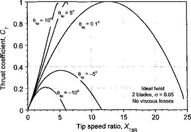
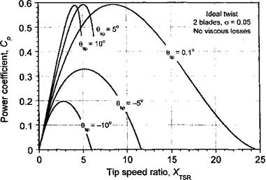
Representative results from the BEMT are shown in Figs. 13.10and 13.11 for a rotor with ideal blade twist operating at different blade pitch angles. No nonideal losses are assumed in this case, (i. e., only ideal-induced losses are present). From results such as these, the power coefficient at a fixed rotor speed can be derived for different wind speeds. For variable pitch
|
Figure 13.10 Representative thrust produced on a wind turbine as a function of tip speed ratio using the BEMT for various pitch angles. No nonideal losses. |
turbine blades, the power coefficient can be determined over a range of pitch angles and wind speeds. It is seen that a shallow blade pitch allows for energy extraction over a wide range of wind speeds; neither large positive nor negative pitch angles allow for efficient operation. Recall that the BEMT is valid only for values of 0 < a < 0.5, so the curves cannot be defined for all wind speeds and all pitch angles unless empirical corrections are used (see Section 13.8.3).
|
Figure 13.11 Representative power output produced from a wind turbine as a function of ’ tip speed ratio using the BEMT for various pitch angles. No nonideal losses. |
|
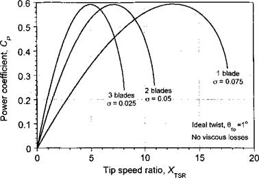
Figure 13.12 Representative power output produced from a wind turbine for different numbers of blades as a function of tip speed ratio using the BEMT. No nonideal losses. |


