Combined Source and Doublet Method
As the first example for this approach let us use the combination of source and doublet elements on the surface. This means that each panel will have a local source and doublet strength of its own. Since Eq. (11.60) is not unique, either the source or the doublet values must be specified. Here the inner potential is selected to be equal to Ф* and for this case the source strength is given by Eq.
(9.12) as
о^Пу-Q» (11.61)
Since the value of the inner perturbation potential was set to zero (or
(ф* = ф,) Eq. (11.60) reduces to
+ = 0 (11.62)
/=i i=і
This equation (boundary condition) is specified at each collocation point inside the body, providing a linear algebraic equation for this point. The steps toward establishing such a numerical solution are as follows:
Selection of singularity element. The velocity potential at an arbitrary point P (not on the surface) due to a constant-strength source element was derived in the panel’s frame of reference in Eq. (10.19):
Ф = ~ {(* — *1) In [(* – *i)2 + z2] – (де – x2) In [(де – x2)2 + z2]
+ 2z(tan-1 — ———— tan-1 —-—■) | panel coordinates (11.63)
JC — ДС2 ДС-ДСі/J
and that due to a constant-strength doublet element in Eq. (10.28):
Ф = – tan-1 — —————- tan-1 —-— panel coordinates (11.64)
2л L де — дг2 jc-jcJ
These equations can be included in two subroutines that calculate the potential at point (де, z) due to the source and doublet element j:
ДФ* = PHICS (Oj, x, z, xjt Zj, Xj+i, zi+l) (11.65)
ДФа = PHICD (Ц), x, z, xh zjt xj+l, zj+x) (11.66)
These subroutines will include the transformation of the point (де, z) into the panel coordinates (e. g., in Eq. (11.23a)) and it is assumed that these potential increments are expressed in term of the global дс-z coordinates. However, since the influence coefficients depend on view angles and distances between points, the transformation of ДФ back to the global coordinate system can be skipped.
Discretization of geometry. The N +1 panel corner points and N collocation points are generated in a manner similar to the previous example of the constant-strength source (Fig. 11.18). However, now the internal Dirichlet boundary condition will be applied and therefore the collocation points must be placed inside the body. (Usually an inward displacement of 0.05 panel lengths is sufficient—but attention is needed near the trailing edge so that the collocation point is not placed outside the body. In the case where the self-induced influence is specified by a separate formula, then for simplicity the collocation point can be left at the center of the panel surface.)
Influence coefficients. The increment in the velocity potential at collocation point і due to a unit-strength constant source element of panel j is obtained by using Eq. (11.65):
Ьц = PHICS {oj = 1, Xj, z„ xJt Zj, xl+l, z/+1) (11.67)
and that due to the same panel but with a unit-strength doublet:
c(> = PHICD (fij = 1, Xj, Zj, Xj, Zj, xJ+u zj+l) (11.68)
Note that this calculation is simpler than in the case of the velocity boundary condition, which required the computation of two velocity components and a multiplication by the local normal vector.
Also the influence of the doublet panel on itself (using Eq. (10.31)) is
c„ = § (11.69)
and for the source the self-induced effect can be calculated by using Eq. (11.67).
Determination of the influence of the doublets at each of the collocation points will result in a N x N influence matrix, with N + 1 unknowns (where the wake doublet fiw is the (N + l)th unknown). The additional equation is provided by using the Kutta condition (see Fig. 11.20):
(цг – pN) + pw = 0 (11.36)
Combining this equation with the influence matrix will result in N +1 linear equations for the influence of the doublets:
|
Jcu |
cn………………… |
C1N |
Cl W |
lnA |
|
|
N+1 N+l |
I C21 |
^22 …………. |
C2N |
Сг w |
1 1*2 |
|
X 2 Сц/ij— |
… |
…………………….. |
|||
|
-=i j=i |
I CNl |
CAI2 ………… |
CNN |
CNW |
Pn |
|
l |
О о |
-1 |
1/ |
By replacing (iw with fiN – /ij from Eq. (11.36), the order of the above matrix can be reduced to N. The first row, for example, will have the form
(Cn — + Cj2(i 2 + ■ • • + (с1Лг + С1(у)до ДГ
and only the first and the Mh columns will change due to the term ±ciW. We can rewrite the doublet influence such that
fly = Cjj j Ф 1, N
fl/i= cn — ciW j = l (11.70)
fl/TV = Cl7V + CiW j = N
With this definition of the doublet coefficients and with the 6,-, coefficients of the source influence, Eq. (11.62), specified for each collocation point 1—> N,
will have the matrix equation form
= 0 (11.71)
Establish RHS vector. By specifying the source strength at the collocation point, according to Eq. (11.61), the second matrix multiplication can be
equation, thus
fRHSi’ RHS2
і RHS,
![]() aN2> ■ ■ ■ , <*NNi
aN2> ■ ■ ■ , <*NNi
with N unknown values цк, which can be computed by solving this full-matrix equation.
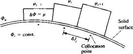
Calculation of pressures and loads. Once the strength of the doublets fx, is known, the potential outside the surface can be calculated. This is shown schematically in Fig. 11.26, which indicates that the internal perturbation potential Ф, is constant (and equal to zero) and the external potential Фи is

![]()
 FIGURE 11.26
Doublet panels on the surface of a solid boundary.
equal to the internal potential plus the local potential jump /x across the solid surface:
Фи = Ф, + /і (11.74)
|
ЭФ*и ai |
The local external tangential velocity component above each collocation point can be calculated by differentiating the velocity potential along the tangential direction:
where / is a line along the surface. For example, the simplest numerical interpretation of this formula is
= —Д/— + 6,. (11.76)
where Alj is the distance between the two adjacent collocation points, as shown in the figure. This formulation is more accurate at the jth panel second corner point and can be used to calculate the velocity at this point. The pressure coefficient can be computed by using Eq. (11.18):
![]()
 (11.77)
The contribution to the lift coefficient is then
AC,. = – Cp. Ц cos a, (11.78)
where A lj and ay are shown in Fig. 11.21. The total lift and moment are obtained by summing the contribution of each element:
L=2ALy (11.79)
/=1
N
Af0 = 2 АСДдсу cos a) (11.80)
,=і
and the nondimensional coefficients can be calculated by using Eqs. (11.12) and (11.13).
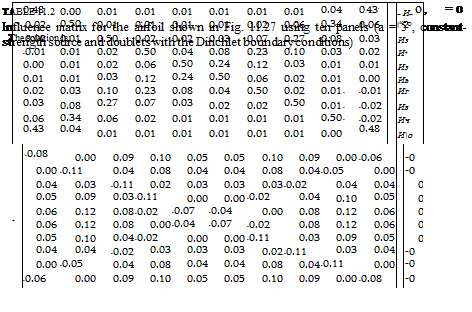
Example 1 Lifting thick airfoil. A short computer program (Program No. 8 in Appendix D) was prepared to demonstrate the above method and the same airfoil geometry was used as for the previous examples. Table 11.2 shows the
|
~иГ |
-0.1795420 |
”0.8” |
||
|
Иг |
-0.1691454 |
0.7 |
||
|
Из |
-0.1914112 |
0.01 |
||
|
И4 |
-0.2294960 |
-0.07 |
||
|
Из Ив |
= |
-0.2296733 -7.9113595×10 2 |
RHS, = |
-0.13 -0.12 |
|
Иг |
9.1565706 х 10“2 |
-0.05 |
||
|
Ив |
0.2577208 |
0.03 |
||
|
Ич |
0.3524704 |
0.08 |
||
|
И ю |
0.3651389 |
0.09 |

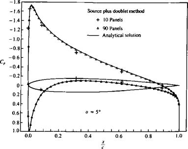
numeric equivalent of Eq. (11.71) for N= 10 panels, along with the RHS vector and the solution vector (of the doublet strengths). These results are plotted in Fig. 11.27, which shows that even with such a low number of panels a fairly reasonable solution is obtained. When using a larger number of panels (N = 90) the solution is very close to the analytic solution at both the leading and trailing edges. As mentioned earlier, the potential-based influence computations (Eqs. (11.67) and (11.68)) and the pressure calculations (of Eq. (11.76) or Eq. (11.38)), seem to be computationally more efficient than the previous methods.
|
FIGURE 11.27 Chordwise pressure distribution on a symmetric airfoil, using 10 and 90 panels (combined source/doublet method with Dirichlet boundary condition). |


