CONTROL OF STREAMLINE BODIES
Any rocket-powered vehicle can be controlled by proper deflection of the jet exhausting from the base. All other streamline bodies have to be steered by means of flaps (rudders, elevators, ailerons) attached to their tail end.
Flap Theory, as presented in the “control” chapter is based upon the concept of two-dimensional circulation. In slender wing and/or body shapes, circulation is obtained through a different flow pattern, id est around the lateral edges. Therefore, an approach to the effectiveness of a trailing-edge flap is required, different from the two – dimensional type as in conventional control surfaces. In a small-aspect-ratio wing, downwash is “complete” and maximum, at and past the trailing edge. Deflection of a flap from that edge is the equivalent of placing a same-size flap behind the “wing” (at some small distance) within a field of flow having a downwash angle £ = — oC. The lift produced by the flap is thus expected to be
ACl= (S^/S)(dCL /doc )^cA (50)
where “f” indicates “flap”, and where the flap’s lift-curve slope corresponds to its aspect ratio b^/c^. If someone objects to this concept saying that a flap linked to the trailing edge of a body does not permit circulation to develop, it can be said that circulation does get around the lateral edges of the body (and of the flap).
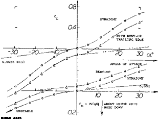
Airplane Ski. There is very little information available regarding the effect of what we may call trailing-edge flaps used in combination with streamline or other slender bodies. The bent-up trailing edge of the airplane ski in figure 43, can be considered to be a flap, however. Interpretation is as follows:
a) The linear lift curve slope cannot very well be higher than indicated by equation 3. Based on plan-form area, the slope may thus be
dCL /doc = 0.2 (0.0274) = 0.0055 where 0.2 = aspect ratio.
b) On the basis of (a) the non-linear component is found to be in the order of
CN2 =3.3 sin2 oC
c) Combining the moment derivative dC^ /dCL = 0.0020 with the lift curve slope as in (a), the neutral point is found to be 0.0020/0.0055 = 0.36 of the length-/, ahead of the hinge axis.
The cross force coefficient as in (b) may seem to be very high. There is a number of similar values presented, however, in Chapter VII of “Fluid-Dynamic Drag”. It appears that low-aspect-ratio sharp-edge flat plates (and similar shapes) are very effective in producing the cross-flow type of lifl. As mentioned before in this chapter, the coefficient should not be expected to be identical with the drag coefficient at oC = 90° , which is CDo ~ 2.
|
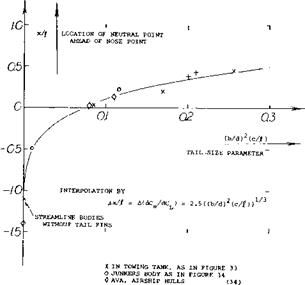
+ FROM OTHER SOURCES Figure 41. Statistical evaluation of the stabilizing effectiveness of fins attached to the end of streamline bodies. |
Bent-Up Trailing Edge. For all practical purposes, bending up the trailing end of the ski, does not affect the nonlinear lift component. The constant lift increment as seen in figure 42, can be expected to be the same as that due to a flap. Depending upon the flap’s aspect ratio b/c^, it contribution to the lift of the ski will be
A CL = (Ср Ц) (dCL /doc)/ = (h/O (dCL /do£) (55)
where Cp. = chord length of the flap, and h = c^cf = height to which the trailing edge is bent up. The lift-curve slope of the flap can be approximated by
dor/dCL =11+ 20/A ^
dCL/doc = 1/(11 +20 Cp/b) (56)
For the ski in figure 43, the equivalent flap chord is approximately Cp = 0.5 b, os that dCL /doc = 0.048. For hЦ = 0.062, a ACl = 0.062 (0.048) 180/ir =0.17, is thus obtained, while the experimental differential is between 0.15 and 0.16.
(36) As expllined in the first longitudinal chapter, the horizontal tail of an airplane is cut in two (so to speak) by the fuselage wake.
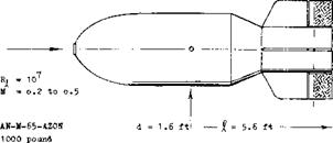
A Radio-Controlled Bomb is shown is figure 44. Deflection of the rudder produces differentials of lateral force and yaw moment, essentially independent of the angle of sideslip (plus/minus 20° ) and the Mach number (M = 0.2 to 0.5). For practical purposes, the variations are also linear in /5 and <f, so that the derivatives tabulated in the illustration, give a full description of the aerodynamic characteristics.
Analysis is as follows:
 a) The moment arm of the lateral force due to rudder deflection is 0.007/0.0015 = 0.47 of the body length, aft of the CG. The center of force coincides with the geometric center of the flaps.
 b) Assuming the effective aspect ratio of the rudder flaps (behind hinge line) to be A_p = bT/c^ = 5.3, the lift curve slope may be (dQ Idoc)^ = 0.07. Using equation 50 the effectiveness may then be
dCyJdtf = (Sp /S0 )(dCL /doC =
0.22 (0.07) = 0.015 (57)
 Figure 43. Longitudinal characteristics of the model of an airplane ski (34,b).
|
|
|
= 1.5(Ю)6 |
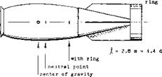
model scale 1 to 4 tested in open wind tunnel
dCL /dcK = O.010
= O.013 with ring
Figure 42. Static stability (position of neutral point) of 1000 kg bomb, tested in the Junkers wind tunnel (39,b).
There are certain assumptions in (b) which have not been confirmed yet by experiment or analysis. The advantage of equation 57 over the usual method of calculating effectiveness (as presented in the “control” chapter) is the fact that the tail contribution to dCy ld/*> does not have to be known. The fins are considered to be part of the body.
(38) Lifting characteristics of rocket vehicles:
a) Kelly, “Scout” with Flare, NASA TN D-794 & 945 (1961).
b) Potter, Multiple Fins, J Aeron Sci 1955 p 511.
Airship Rudder. Directional characteristics of the experimental hull shape in figure 38 are discussed in the section dealing with “stability”. As far as the rudder is conserned, its deflection changes the yaw moment by a constant amount (independent of the angle of yaw); thus A(dCy/d<f ) and A (dC^dcf constant. This means
that the rudder changes the body’s basic circulation; regarding cross flow, the rudder area is too small to show an effect. As seen in part C of the illustration, force and moment increase in proportion to sinrf, up to some 20° deflection. The center of force, corresponding to А хЦ = 0.003/0.006 = 0. 50, is as indicated in the drawing, somewhat ahead of the rudder, withing the wedge-shaped tail end of the hull. Considering the body to be a low-aspect – ratio wing, the rudder is a “flap”. Deflection of this flap evidently increases the longitudinal circulation around the body. As in flapped control surfaces (such as a horizontal tail, for example) we have an effectiveness ratio based on the linear derivative (dCy ДІД):
(dCy/dcf )l(dCyld/3) = d^ldd = 0.36
This looks like a very high value for the rudder area ratio S^./(d-f) = 1.3%. However, it is shown in Chapter IX, that the effectiveness ratio increases as the aspect ratio is reduced. Considering the hull’s thickness ratio dЦ = 0.12, to be the aspect ratio, the ratio of 0.36 can be understood.
“Akron”. Another example for this method of analysis, is the airship “Akron”:
|
7 |
= 785 ft |
length overall |
|
V |
= 7.4(10)b |
ft3 displacement volume |
|
d |
= 130 ft |
maximum diameter |
|
= 7400 ft2 |
exposed horizontal fins |
|
|
Sf |
= 1100 ft2 |
elevator, aft of hinge line |
|
bH |
= 1.09 d |
span of fins |
The. lift derivatives (based on d2) as tested on a 1/40 scale model (TR 432) are:
dC {d /doc: = 0.026 due to angle of attack
dC /dS = 0.006 due to elevator deflection
For the flap-area ratio S^/d2 = 1100/1302 = 6.5%, for bw /cf = 10, and a lift-curve slope (dCL /do£)p ■= 0.085, equation 50 yields a dCLd /dcT = 0.065 (0.085) = 0.0055, which is close to that which was tested around zero angle of attack.
|
M up to 1.0, at sea level |
Turning. It is described in the section dealing with “stability”, that airships are not really stable. The plot of C^CJ as in figure 38, shows that balance and stability of the airship (with control surfaces kept neutral) both in pitch and ir yaw, is obtained at CLb or Cyb = 0.18, where oc or ^ =26°. Conditions of an airship hull when turning are different, however, as explained in context with figure 28. For a difference in the angle of wind against body axis, between the center of buoyancy and the stern, say of 15°, the force in stern and fins may be doubled. This means a tremendous “resistance” against turning.
derivatives as tested (39,d)
dCnn/d(3 – о.013 acnj/d£ = о. 007
dCyVdp * o.070 dCYyd& » O.015
coefficients based on frontal area
Figure 44. Directional characteristics of a radio-controlled bomb, tested (39,d) full scale in a wind tunnel.
(39) Fin-stabilized ‘‘flying” bodies:
a) Junkers, Fin-Stablilized Tank, Dct D-6548 (1940)
b) Junkers, Bombs, Dcts D-6549 & 6573 (1940).
c) Kempf, In Towing Tank, NACA TM 1227.
d) Pearson, 1000 Pound Bomb, NACA W’Rpt L-131 (1944).
(43) Control of reentry-type vehicles:
a) Paulson, Cruciform Delat, NACA W’Rpt L-734.
b) Paulson, Trailing Edge Control, NASA Memo 4-11-59L.
(44) Comparison between equations (2) and (21) indicates that in a spheroid (or ellipsoide) the positive force in the forebody and the negative force in the afterbody, each has a moment arm equal to 1/3 of the body length.


