Flight Tests
Using PtOEP in silicone resin, McLachlan et al. (1992) measured the surface pressure distributions on a fin attached to the underside of an F-104 fighter jet in flight. A self-contained data acquisition system was installed inside the fin, which consisted of an 8-bit digital video camera and an UV lamp triggered remotely to excite PSP. PSP was applied to a Plexiglas panel mounted flush with the fin. The luminescent emission from PSP was transmitted through the Plexiglas into the fin where it was subsequently recorded by the video camera. Two tests were flown at night at the Mach numbers 1.0-1.6 at altitudes between 30,000 and 33,000 ft. Pressure taps mounted on the fin were used to calibrate PSP in-situ. Results showed a favorable comparison to the pressure tap data at the Mach numbers greater than 1.3, and the accuracy of about ±0.24 psi was reported. Houck et al
(1996) performed flight tests using PSP on a Navy A-6 Intruder where PSP was painted on an Mk76 practice bomb. The data acquisition system consisted of a battery-operated strobe light for excitation that was synchronized with a Nikon 50mm film camera used to measure the luminescent emission. This system was self – contained and mounted onto a bomb rack adjacent to the practice bomb. Three night flights were flown at altitudes between 5,000 and 10,000 ft at the Mach numbers 0.4-0.82. After flight, the negative films were developed and digitized by projecting them onto a 14-bit CCD camera. No in-situ calibration was done such that only qualitative results were presented and the temperature effect was unable to be accounted for. Using a similar film camera system, Fuentes and Abitt
(1996) measured the pressure distributions on a Clark-Y airfoil mounted underneath the wing of a Cessna 152 aircraft. In general, issues associated with film developing and processing make film-based systems more difficult for quantitative measurements.
Using a portable 2D phase-based laser-scanning lifetime system, Lachendro et al. (1998, 2000) conducted in-flight PSP measurements on a wing of a Raytheon Beechjet 400A aircraft. Flight conditions were chosen to produce such a wing pressure distribution that could be easily detected by the laser scanning system. Thus, two flight conditions were considered: (1) 31,000 ft and Mach 0.75, and (2)
21,0 ft and Mach 0.69. These Mach numbers represented the maximum cruise Mach number obtainable at the respective altitudes. Also, pressure data in the above flight conditions were available from a flight test previously conducted by Mitsubishi Heavy Industries (MHI). Since this aircraft was a derivative of the Mitsubishi-designed Diamond II, it had been extensively studied in flight and wind tunnel testing (Shimbo et al. 1999). The previous data were used to validate the feasibility and accuracy of in-flight PSP measurements. The minimum and maximum pressures and temperatures from both numerical calculations and MHI flight tests were used as the design boundaries for selecting proper PSP and TSP formulations for in-flight tests. A total of six in-flight tests were made. Three tests were conducted at Purdue University on a university-owned and – operated Beechjet 400A aircraft; three other tests were performed at Raytheon Aircraft Company in Wichita, Kansas on a Beechjet 400A aircraft designated solely for inflight testing. In order to make in-flight PSP measurements, a lifetime-based or phase-based technique is more suitable because this technique does not require reference signal (or image) used in conventional intensity-based systems and therefore it is not affected by wing and fuselage deformation. The lifetime-based technique is also insensitive to the ambient light from the Moon and stars. Additionally, the system must be able to collect data over a large distance. In the tests conducted by Lachendro et al. (1998, 2000), PSP and TSP measurements were made at distances greater than 16 feet away from the photodetector. To improve the SNR, a coherent light source such as a laser should be used. A compact laser scanning system was specially designed for phase-based PSP and TSP measurements at large distances.
The laser scanning system was designed to be as small as possible so as to easily fit inside the aircraft. In addition, it was built to be robust and allow easy modification to optical arrangement. The laser scanning system consisted of scanning/positioning and data acquisition parts. Two 5-in diameter Velmex programmable rotary tables were mounted orthogonally to each other via an aluminum angle bracket. Mounted onto the vertical stage was an 8×5 in aluminum backing plate that served as the mounting surface for the laser scanning system plate. This allowed the scanner to position the laser spot on a wing. The rotary stages were controlled through the serial port of a PC using a Velmex’s NFS-90 stepper motor controller. A Lab VIEW interface program allowed for generation of a series of points distributed across a wing surface, and then a surface grid formed by these points could be scanned repeatedly by the system with a minimal deviation of the points from one scan to another. The angular positioning resolution was ±0.0125° and the corresponding position resolution was ±1 mm at a distance of 16 feet.
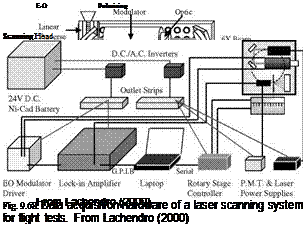
Figure 9.67 shows the laser scanning system plate mainly comprised of a UniPhase solid-state Nd:YAG laser (532 nm and 50 mW), a PMT, and an electrooptic (E-O) modulator with a driver. Data acquisition hardware is shown in Fig. 9.68. For phase-based measurements, a laser beam was passed through the E-O modulator (Lasermetrics model 3079FW) for modulation. The input beam to the E-O modulator was polarized using two Glan-Thompson polarizers. The first polarizer was placed at the output of the laser to control the intensity, whereas the second polarizer mounted at the end of the E-O modulator controlled the depth of modulation. The beam was then passed through a Melles Griot 6X beam expander/focuser, allowing for tightly focusing the scanning spot at a distance greater than 1 m. The luminescent emission from PSP was collected through a 3in convex lens (f-number 1.86) and then was focused through a spatial aperture located in the front of a long-pass filter (> 570 nm). The filtered emission was passed into a PMT (Hamamatsu Model HC-120), and the PMT output was sampled by a 16-bit A/D converter in a lock-in amplifier (EG&G model 5302). The two-channel lock-in amplifier was capable of simultaneously measuring the magnitude and phase of the luminescent signal. Data from the lock-in amplifier was acquired through the GPIB interface into a PC using a LabVIEW program that coordinated positioning of the scanning system with data acquisition. The luminescent intensity and phase were recorded at each specified location of the laser spot on the wing surface and saved for subsequent data analysis.

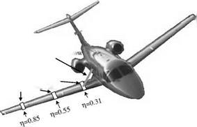
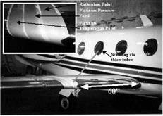
Four PSP formulations, Ru(dpp) PSP and three PtTFPP PSPs in different binders, were developed for in-flight tests. These paints were chosen based on their overall performance in a pressure range of 1-7 psi and a temperature range of -50 to 0°C. PtTFPP in the FEM co-polymer binder was much less temperature – sensitive than other paints. Due to photosensitivity of the paints, they were applied to the wing only just before a flight after the wing was cleaned with an ethanol-based solvent. For the first flight test, two PSPs and one TSP were used and sprayed separately onto 75-in long and 3-in wide strips on an adhesive-backed monocoat film. As illustrated in Fig. 9.69, the strips wrapped around the leading edge and positioned streamwise to the trailing edge. For the other three flight tests, as shown in Fig. 9.69, the painted strips were placed at 31%, 55% and 85% spans that corresponded to the locations in the MHI flight test. At each location, PSP and TSP strips were placed side by side.
|
|

532nm Nd: Yag laser scanning from cabin windo
Mylar strips coated, with PSP and TSP
Fig. 9.69. PSP and TSP installation for flight tests. From Lachendro (2000)
Somewhat unexpectedly, Lachendro et al. (1998, 2000) found a considerable temperature variation across the wing chord that was caused by wing fuel tanks warmed by moving fuel and relatively cooled stringers. Due to poor temperature sensitivity of TSP over the testing temperature range, the temperature effect of PSP could not be corrected based on TSP data. Instead, they had to use a simple heat transfer model to estimate the mean temperature on the wing in the flight conditions. The chordwise pressure distributions were obtained at 31%, 55% and 85% span. Figure 9.70 shows the pressure coefficient Cp given by PSP at 21,000 ft and Mach 0.69 compared to the existing MHI fight test data. The distribution of Cp was calculated from a priori calibration relation of PSP using the mean wing temperature of -5°C estimated based on a heat transfer model. It was noted that the first data point near the leading edge in the MHI flight test data was likely erroneous and it could be disregarded. Near the trailing edge after x/c = 0.75, the PSP data were significantly lower than the MHI flight test data. This was because the mean temperature of -5°C used for PSP data reduction over the whole wing section led to an underestimated value of Cp at the thin trailing edge that was actually colder than the middle portion of the wing. Since the temperature variation caused by moving fuel was not large at 21,000 ft, the PSP data in this case did not exhibit a significant pattern produced by the temperature variation across the wing section.
 |
-1.4


