Flow through Pipes
Fluid flow through pipes with circular and noncircular cross-sections is one of the commonly encountered problems in many practical systems. Flow through pipes is driven mostly by pressure or gravity or both.
Vi
(a)
Steady laminar flow
/V’ (measured from V)
V
t
(b) ![]()
![]()
![]() Steady turbulent flow Vi /V’ (measured from V)
Steady turbulent flow Vi /V’ (measured from V)
t
(c) Unsteady turbulent flow
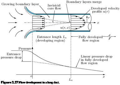
Consider the flow in a long duct, shown in Figure 2.27. This flow is constrained by the duct walls. At the inlet, the freestream flow (assumed to be inviscid) converges and enters the tube.
Because of the viscous friction between the fluid and pipe wall, viscous boundary layer grows downstream of the entrance. The boundary layer growth makes the effective area of the pipe to decrease progressively downstream, thereby making the flow along the pipe to accelerate. This process continues up to the point where the boundary layer from the wall grows and meets at the pipe centerline, that is, fills the pipe, as illustrated in Figure 2.27.
The zone upstream of the boundary layer merging point is called the entrance or Bow development length Le and the zone downstream of the merging point is termed fully developed region. In the fully developed region, the velocity profile remains unchanged. Dimensional analysis shows that Reynolds number is the only parameter influencing the entrance length. In the functional form, the entrance length can be expressed as:
![]() f (p, V, d, V)
f (p, V, d, V)
![]()
 |
fj pPVd i
where p, V and Vare the flow density, velocity and viscosity, respectively, and d is the pipe diameter. For laminar flow, the accepted correlation is:
At the critical Reynolds number Rec = 2300, for pipe flow, Le = 138d, which is the maximum development length possible.
|
L ^ 4.4 (Red)6 . d |
 |
For turbulent flow the boundary layer grows faster, and Le is given by the approximate relation:
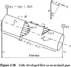
Now, examine the flow through an inclined pipe, shown in Figure 2.28, considering the control volume between sections 1 and 2.
Treating the flow to be incompressible, by volume conservation, we have:
![]()
![]() Q2 = constant
Q2 = constant
Q = V, = Q Ai 2 A2’
where Qi and Q2, respectively, are the volume flow rates and A1, A2, V1 and V2 are the local areas and velocities, at states 1 and 2. The velocities V1 and V2 are equal, since the flow is fully developed and also Ai = A2.
 |
|
By incompressible Bernoulli’s equation, we have:
where Az = (z1 — z2) and Ap = (p1 — p2). That is, the head loss (in a pipe), due to friction is equal to the sum of the change in gravity head and pressure head.
By momentum balance, we have:
![]() ApnR2 + pg(nRz) AL sin0 — rw(2nR) AL = m(V1 — V2) = 0.
ApnR2 + pg(nRz) AL sin0 — rw(2nR) AL = m(V1 — V2) = 0.
Dividing throughout by (nR2)pg, we get:
![]() ——- + AL sin в
——- + AL sin в
Pg
But AL sin в = Az. Thus:
Ap 2tw AL
—- + Az =————
Pg Pg R
Using Equation (2.72), we obtain:
In the functional form, the wall shear tw may be expressed as:
![]() tw = F(p, V, p, d, e),
tw = F(p, V, p, d, e),
where p is viscosity of the fluid, d is the pipe diameter, and e is the wall roughness height. By dimensional analysis, Equation (2.75) may be expressed as:
<2-76)
where f is called the Darcy friction factor, which is a dimensionless parameter.
Combining Equations (2.74) and (2.76), we obtain the pipe head loss as:
This is called the Darcy-Weisbach equation, valid for flow through ducts of any cross-section. Further, in the derivation of the above relation, there was no mention about whether the flow was laminar or turbulent and hence Equation (2.77) is valid for both laminar and turbulent flows. The value of friction factor f for any given pipe (that is, for any surface roughness e and d) at a given Reynolds number can be read from the Moody chart (which is a plot of f as a function of Red and e/d).
It is essential to note that in our discussions here it is mentioned that, decrease of pipe area due to boundary layer, results in increase of flow velocity. This is possible only in subsonic flows. When the flow is supersonic, decrease in area will decelerate the flow [2].


