Hypersonic Viscous Flow: Numerical Solutions
In previous chapters we have studied the analytical and experimental work related to viscous hypersonic flow past flat plate at zero angle of attack. Now, we can extend those to further study hypersonic flows with the aid of computational fluid dynamics.
Let us start with the solution of viscous hypersonic boundary layer equations. If we take x coordinate as the direction parallel to the surface and z coordinate as the direction normal to the surface the set of equations reads as
Continuity: Oq + Oqu + = 0 (7.88a)
1 0t 0x 0z
/0“ 0“ 0u Op 0 / 0u
![]()
![]()
Momentum: Ча + “a!+=-aX + &№ (7:88b)
for unsteady flow. Here, in addition to velocity components u and v, h shows the enthalpy and T denotes temperature where pressure p is as usual provided from outside. In order to solve the boundary layer equations about a blunt body, we start with the stagnation flow solution. Equations 7.88b, c, are partial differential equations. They can be transformed to ordinary differential equations with Illingworth transformation, i. e. П = /о peUepedx and g = Ue Д/2П /0 qdz, and the non dimensional f (g) = u/Ue and non dimensional enthalpy then reads g = h/he
(Cf )’ + f” = f’)2 – g (7.89a)
(Cg’)’+ Pfg’ = 0 (7.89b)
Here, Pr is Prandtl number, and C = pp/(pepe) (White 1991). If we use the power law for the viscosity variation with temperature for the perfect gas we obtain C = g(n-1).
For air, taking n = 2/3, makes Eqs. 7.89a, b in terms of g as the independent variable
f’ – f + g1/3ff’ ‘ + g4/3 – g1/3(f’ )2 = 0 (7.90a)
3g
g” – g + Prg1/3fg’ = 0 (7.90b)
3g
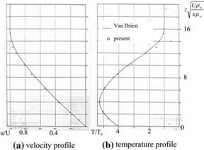
Equations 7.90a, b are solved with an iterative method to obtain the stagnation speed and temperature which satisfy the wall and the edge conditions. These velocity and the temperature values are used as the initial station to start solution of the parabolic Eqs. 7.89a, b with a marching technique. Eqs. 7.88a, b are solved with finite difference as explained in Appendix 10. The calibration of the scheme is made with the hypersonic flow past a flat plate at free stream Mach number of 8. In this bench mark test, the wall to edge temperature ratio is considered 4 as shown in Fig. 7.23a, b (Oksuzoglu and Gulcat).
After observing the agreement with the present solution and the Van Driest solution Fig. 7.23, the numerical procedure is applied to the hypersonic flow past circular cylinder. The pressure distribution for the circular cylinder is provided by the Newtonian Flow.
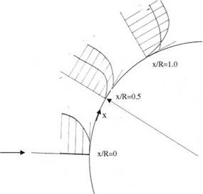
Shown in Fig. 7.24 is the hypersonic boundary layer flow about the circular cylinder at M = 8, Re = 10,000, and Pr = 0.75. The stagnation flow solution is
![]()
![]()
 |
 |
 done with Eq. 7.90a, b at x/R = 0, and the boundary layer edge to wall velocity ratio is taken as 2 for temperature profiles where the wall appears to be cold.
The studies and the related examples for the viscous hypersonic flow are so far for the flows having free stream Mach numbers 8 or smaller. During re-entry when the free stream Mach number is greater than 8, the oxygen and the nitrogen molecules disassociate with speed and altitude as shown in Fig. 7.19. For this reason, as done before, we have to include the chemical reactions in our computations. Since the viscous effects are to be seen near the wall, we have to see whether the wall is a catalytic or not, and add the diffusion terms to the equations together with altering the boundary conditions at the wall in terms of heat
conduction. For this reason, let us first determine the mass diffusion coefficient in terms of Fick’s law. The Fick’s law gives the amount diffusion between the species 1 and 2 as follows: – pD12 grad cj_, where cj is the mass fraction of the specie 1. Here, D12 is the coefficient of diffusion whose values are given in tables in literature to be used in computation in low density flows. The viscous solutions based on the mass diffusion require adding the relevant terms to Navier-Stokes equations. Now, let us re-write the boundary layer equations, Eq. 7.88, by adding the diffusion terms. The continuity and the x momentum equations written for the total species, Eq. 7.88a, b, retain their original forms. The diffusion terms need to be added to the continuity of the species and the total energy equation. The continuity of specie i then reads as
де, 0ci 0 ( 0еД. .
quaX+qw0Z = 0z(qD1’–0Z + wi (7:91)
The energy equation then becomes
Here, k is the time dependent heat conduction coefficient. Since there are more than one specie, the values of k and i are computed with a special averaging method (Anderson 1989).
The boundary layer equations, given by Eqs. 7.91 and 7.92 together with the total continuity and the momentum equations, 7.88-a, b, with chemical reactions and the wall boundary conditions were seen in the literature starting from mid 1980s. An example to this sort of elaborate work is the study performed by Aupoix et al. (1987). In their study, the two dimensional boundary layer equations at the symmetry plane of the lower surface of the space shuttle are solved at free stream Mach number of 23.4 considering a catalytic and non catalytic wall. Five species, disassociation of O2, N2 into O and N, and formation of NO are involved in reacting flow together with catalytic wall conditions. The conclusions of the afore mentioned work is as follows: (1) wall catalysity and the wall temperature have an effect on the heat flux and the displacement thickness, (2) the surface friction is independent of real gas effects, (3) chemical reactions for a few number of species are sufficient, and (4) simple diffusion models yield accurate solutions. In addition, the heat flux qw at the wall is given by diffusion of 2 species as follows
qw = – k0T – PD12 X hi0z (793)
i w
For the case of adiabatic wall equating Eq. 7.93 to zero is sufficient. In reacting flows, on the other hand, the mass fraction of species is unknown in the equations; therefore, while solving the continuity of the species, the catalytic effects which determine rates of reaction at the wall are to be considered. The expression which gives the catalytic formation of species and their diffusion into the flow is as follows
For a non catalytic wall, Eq. 7.94 is set to zero to get (|y-)w = 0. On the other hand, for fully catalytic walls the rate of chemical reactions is infinite; therefore, the mass fractions of the species take their equilibrium chemistry values, i. e., Cj = (c;)eq. For partially catalytic walls, since the chemical reactions take place with finite rates, the specie production rate in Eq. 7.94 is given in terms of the gradient of Ci.
Aupoix et al. (1987) also discovered in their study with catalytic and non catalytic wall at 1,500 K, M = 23.4, and 71 km altitude using 5 and 10 species that the heat transfer rate at the stagnation point is 0.4 MW/m2 for catalytic wall and 0.1 MW/m2 for non catalytic wall. Naturally, reducing the Mach number and the wall temperature reduces the heat transfer.
The non dimensional boundary layer equations for hypersonic flow help us to predict the flow parameters as it was the case for original boundary layer equations. In non dimensionalization we take the velocity, density, enthalpy and the diffusion coefficient at the boundary layer edge as the characteristic values. If we write the non dimensional stagnation enthalpy ho = h + и2/2 in the energy equation then we have
(7.95)
Here, Le = pD12cpfk, is the Lewis number and cpf = Rc;cpi, is the summation of specific heat constants at the frozen flow. According to Eq. 7.95, if the Lewis number is 1 in the boundary layer then the effect of diffusion disappears.
The stagnation point solutions are to be known in order to start the boundary layer solution around blunt bodies. We need to add the term with the Lewis number to Eqs. 7.89a, b. With these terms added, the heat transfer rates at the stagnation point of a wall, catalytic or non catalytic, are provided in terms of the Lewis number by Anderson (1989).
Other than boundary layer equations, the hypersonic viscous reacting flow numerical solutions for the space shuttle at 71 km of altitude with free stream Mach number of 23 were published by Prabhu and Tannehill in mid 1980s. In their study, comparison of equilibrium chemistry solution with the perfect gas solution for the value of у = 1.2 shows that they match with each other. This indicates that at the upper level of atmosphere flight conditions are better simulated using у = 1.2.
Also in mid 1980s, gas kinetic equations were employed to predict the three dimensional flow simulations at the upper level of atmosphere with some degree of slip instead of no-slip condition at the surface (Riedelbauch). In 1990s unsteady three dimensional Navier-Stokes equations were employed for solution of hypersonic aerodynamic problems (Edwards and Flores 1990). In their work,
numerical solutions obtained for chemically reacting flow past a sphere-cone configuration at high Mach numbers and high altitudes are in good agreement with the previous studies in terms of surface pressure and heat transfer rates. The specific heat ratio calculation obtained for the reacting flow gives у = 1.4 before the shock, and its value reaches minimum of 1.2 after the shock.


