Increase in Maximum Lift by Suction
 |
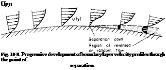
The Karman-Polhausen method is useful for predicting the occurrence of separation as well as transition. The progressive development of the velocity profiles through separation is shown in Fig. 10-8.
At the point of separation
From (10-22) this condition leads to the requirement that the coefficient a must vanish. Thus from (10-23) it holds, with or without suction, that at separation
![]() A = -12.
A = -12.
Suction can be used to ensure that Л is always greater than —12. In the general case the relation between the suction velocity and Л can be determined by numerically integrating the momentum integral equation. However, some insight into the effect of suction on separation can be readily obtained by a method attributed to Prandtl. Prandtl considered the case in which the suction is just sufficient to maintain the separation profile.
In this case du/dy = 0 at the wall so that suction does not influence the values of a, b, c, and d. Hence и becomes
~ = 6h2 – 8h3 + ЗА4.
![]() oo
oo
Notice that (З is not zero, but because of the change in the boundary conditions the effect on the coefficient is the same as if /? were zero; <5* and в for this case are from (10-24):
3*_ _ 2 в _ 4_
T “ 5’ S~ 35
The momentum integral equation can be expanded and put in a slightly different form:
3* + 2 6dUx dS v0 i0
~ur^ + T, + u:-w. (I0’26)
For the separation profile t0 and dO/dx are zero. Hence (10-26) becomes
![]() (10-27)
(10-27)
In addition, from the boundary layer equation applied at the wall
but for the separation profile д2и/ду2 = ЩІІ^/52), so that
![]() ‘ — 12v T/2
‘ — 12v T/2
_(dUJdx)_
The suction required to maintain the separation profile is thus
In terms of the pressure gradient, this can be written as
Thus, as one would. expect, the greater the adverse pressure gradient, the greater the CQ must be to maintain the separation profile.
The foregoing applies only to laminar boundary layers. In order to predict the separation of turbulent boundary layers, recourse must be made to experimental results because of the uncertainties involved with the shearing stresses. The momentum integral equation still holds for the turbulent boundary layer. However, it is usually written in the form
where H is the shape factor defined by (10-11).
Experience has shown that a turbulent boundary separates when Я has a value of approximately 1.8 to 2.4.
The velocity profile in a turbulent boundary layer can be fitted closely by a power law
![]() и _ /у1/и
и _ /у1/и
~ W ‘
For such a form 5*, в, and H can be found from
ё*____ 1_ в n 2
S 1 + n S (1 + иХ2 -1-й) + n
The crux of the problem in studying the turbulent boundary layer lies in obtaining information on H and the wall shearing stress. If this is known, then (10-31) can be integrated. One common assumption is that тolpU2^ is of the same form as for a flat plate:
![]() ч = a
ч = a
pUi (U00e/v)llk’
к and a depend somewhat on Reynolds number. Reference 1 suggests using a = 0.0128 with а к of 4 or a = 0.0065 with а к of 6. In integrating (10-31), since H is increased by 2 and generally does not vary much with x, it is not too unrealistic to use a mean value for Я, say the flat plate value of 1.4 corresponding to an exponent n of 5.
By the foregoing procedure, however, we do not obtain any predicted variation of H with x so that the separation point cannot be predicted by using H as a criterion. To do this the reader is invited to take his choice of the myriad analyses of turbulent boundary layers to be found in the literature.
A practical approach to the problem of preventing separation of the turbulent boundary layer or the upper surface of a wing can be found in Ref. 4. Here the approach was taken to calculate the suction distribution necessary to prevent 0 from growing with x. Also a value of H of 1.5 was assumed. Under these assumptions, since dd/dx = 0, Eq. 10-31 becomes
Vq_ = r0 _ 3.50; dUx Ux ~ pUi Ux dx
![]() or in coefficient form
or in coefficient form
Vo_=C/+ AAi dJA, uaо 2 1 – c„ dx ’
where Cf = turbulent flat plate skin friction coefficient evaluated at the local Reynolds number based on x and Ux,
Cp = (P — P0)/ipUl = local pressure coefficient,
6j = initial value of momentum thickness.
0; can be calculated from methods to be found in Ref. 1 or by the following equation taken from Ref. 4 and credited to Tani.
0; = ^0.44vC/-x6_xJJ’ Ui dx j (10-36)
where xT is the distance from the leading edge measured along the surface to the transition point.
In Ref. 4, Eq. (10-35) was applied to a sailplane and the resulting CQ was calculated as a function of x. From tests of this sailplane with an unflapped wing an average CQ of 0.00316 produced a CLmax of 2.3 with suction, an increase of 0.9 over the solid wing. This increases in Ctmax for this 1300-lb aircraft required less than one air horsepower for the suction.
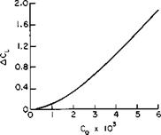
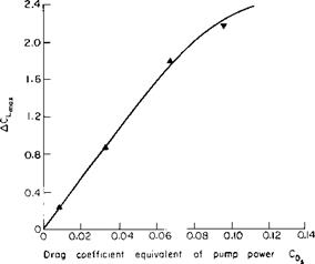
BLC was also applied to light-powered aircraft at Mississippi State University. Porosity was obtained by drilling rows of holes in the surface approximately 0.030 in. diameter and spaced no closer than 0.1 apart. The results interpreted in Ref. 5 are presented in Figs. 10-9 and 10-10. From Fig. 10-9 increments in Ctmax of at least 2.0 are seen to be possible by the application of suction BLC. The power required for this particular installation to accomplish a given ACLmax is represented in Fig. 10-10 as an
equivalent increase in the aircraft drag coefficient. If Ps is the suction power required, then CDs is defined according to
Ps = pV3SCDs.
Actually the BLC system should not be charged for all this power, for, in addition to delaying the stall, the suction reduces the form drag of the
|
Fig. 10-9. Increment in Cimix due to suction BLC. |
wing. I remember clearly the treat afforded me by the late Dr. Raspet of being taken for a flight in a sailplane with BLC. After touching down at near stall with the BLC off, the BLC was turned on and we were able to climb back into the air because of the reduced drag. I also remember that with BLC applied only to the right wing the unbalance in lift produced by
|
Fig. 10-10. Variation of suction power with increment in CLt |
the unsymmetrical BLC was greater than the available aileron control. However, as pointed out in Ref. 4, the use of distributed suction for stall control imposes no severe trim requirements. An important conclusion of this reference is that the technique of distributing suction by means of the momentum equation yields lift increments with much less power than is required by the single-slot systems previously investigated.


