Momentum Theory Analysis for a Wind Turbine
The aerodynamic modeling of wind turbines has spanned the entire range of methods used for helicopter rotors, from engineering models based on blade element-momentum theories, through traditional blade element models combined with inflow or vortex wake theories, to computational fluid dynamics (CFD) methods that solve numerically the Euler or Navier-Stokes equations from first principles. The most fundamental level of analysis of the wind turbine is by means of the classical momentum theory, first developed by Betz & Lock [see Glauert (1935, 1983)]. This one-dimensional approach is very similar to the descending helicopter problem examined in Section 2.13.2. In this case, however, the thrust from the wind turbine is not known a priori and will be a function of the wind speed, rotor speed (rpm), and blade pitch. This means that the problem cannot be solved uniquely using momentum theory by itself and, at a minimum, the blade element theory combined with the circulation theory of lift must be used. The momentum analysis of a wind turbine allows for a first level analysis of the power produced for a given wind speed, however, and can be used to determine the conditions under which the maximum energy conversion from the wind can be obtained.
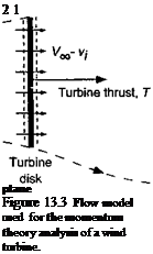
A 1-D model of the control volume surrounding a wind turbine is shown in Fig. 13.3. The wind speed is V^, with the induced velocity in the plane of the turbine being v, . Notice that, to avoid any ambiguity, it is assumed that the velocity is measured as positive when in a downstream direction. At the plane of the turbine, the net velocity is Vqo — vt. In the far wake (well downstream of the turbine) the velocity is Vqq — w. Notice also that because a wind turbine extracts energy from the flow, the velocity decreases downstream of the turbine, From continuity considerations the slipstream boundary (wake) must, therefore, expand. By the application of the, principle of the conservation of mass, the fluid mass flow
rate, m, through the turbine disk is
m = рАІУоо – ы). (13.3)
The change in the momentum of the flow across the disk can be related to the thrust by
T – mVoc-m (Voo – w) ■ (13.4)
Expanding out this equation gives a relationship for the thrust on the turbine in terms of the velocity deficit in the turbine wake, that is,
![]() ru V 00 “T Г ft W — rriuu.
ru V 00 “T Г ft W — rriuu.
The power output from the turbine can be obtained by conducting an energy balance for the system. Basically the work done on the flow to change its kinetic energy must be extracted by the turbine, assuming no viscous or other “nonideal” losses at this stage. The work done on the air by the turbine per unit time, W, is given by
l,1,1 1
W = – m (Voo – w)2 – – mV£ = ^rnw{w – 2УЖ) = –mw {2У(у0 – w).
(13.6)
Notice that the turbine does negative work on the air (i. e., it decreases its kinetic energy). Therefore, the turbine extracts power from the airstream and this operating condition is known as the windmill state, for obvious reasons. More usually this state is referred to as the windmill brake state because the turbine in this condition decreases or “brakes” the wind velocity. This means that the power output from the turbine is positive and so
P = T (Voo – ^mw (2Voo – w). (13.7)
Substituting Eq. 13.5 into Eq. 13.7 gives
T (Voo ~ Vi) = іmw (2Voo ~ w) — mw (V» – vt), (13.8)
from which it is apparent that w = 2d,- or u, = w/2. This is the same relationship found for the helicopter in axial flight, as discussed in Section 2.13.2, and so in this case from
Direction
![]() of positive———————— ►
of positive———————— ►
velocity
 00
00
Free-stream
flow
Far downstream
continuity considerations the wake expands downstream of the turbine. It is also apparent that, for the assumed flow model in Fig. 13.3 to be valid, then Vqo — ш > 0 or alternatively that Voo > |w| > 2|i)j|. If this is not satisfied then there is the possibility of two flow directions in the flow near the turbine disk and a unique control volume encompassing only the limits of the disk cannot be defined. This is equivalent to helicopter rotor operation in the turbulent wake and vortex ring state (see Section 2.13.6), for which no exact solution can be found by means of the momentum theory.
In the case of the wind turbine, its thrust is not known (or defined) a priori like in the helicopter problem. Therefore, it is not possible to find the performance of the turbine as a func-
![]()
![]()
 IV* nr»,a /o1n#a rxf ІпгЬіГ’АґІ /аі r»r*i t; ‘TbArAfrvtv*
rviviviiw VU1UV Vi. XUUUWU T ViWl LJ. JLliVi V1V1W)
in the analysis of a wind turbine it is usual to define an induction ratio a as the independent parameter such that a = Uj/ Voo or that и,- = a Vqq. The thrust and power output can then be established as a function of a, if this value can be found (calculated). It will be apparent that the larger the value of a the more the flow is slowed as it passes through the turbine.


