Supersonic wing shapes – aerofoil sections
What then of the shape of the aerofoil section?
The proviso here is that it must be thin – or to be more correct, that it must have a low thickness/chord ratio – but apart from this it doesn’t seem to matter very much. Straight lines are as good as, or better than curved surfaces; and there is no objection to corners, even sharp corners – within reason.
A flat plate would make an excellent supersonic wing section, but would not have the necessary stiffness or strength; and the easiest way to make it a practical proposition is to thicken it somewhere in the middle, and thickness in the middle leads naturally to the double-wedge, or rhombus shape, which we have already discussed (Fig. 12.9), and which is as good as any other supersonic aerofoil section.
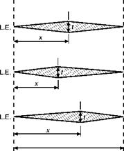
It makes little difference whether the thickest point is half-way back, or more or less; there is little change of drag for xlc ratios between 40 per cent and 60 per cent (Fig. 12.21), and the lift and centre of pressure positions are
not affected at all. But we have always got to consider flight at subsonic speeds and, from this point of view, maximum thickness should be at 40 per cent of the chord rather than farther back; from this point of view, too, it may pay to round the corners slightly.
A variation of the double-wedge is the hexagonal shape (Fig. 12.22). This gives greater depth along the chord and so greater strength, and also makes the leading edge rather less sharp, which has advantages both as regards strength and, as will be considered later, aerodynamic heating.
A bi-convex wing is also quite good (Fig. 12.23), and this is better than the others at subsonic speeds. A bi-convex wing has about the same drag as a double-wedge with maximum thickness rather outside the best range, i. e. at about 25 or 75 per cent of the chord.
Enough has been said about supersonic aerofoil sections to make it clear why the sections in Appendix 1 are all of subsonic type; there would not be much point in giving the contour of a flat plate, or even of a double-wedge – and moreover there is little difference between the lift and drag coefficients of all reasonable shapes, and still less difference in the positions of centre of pressure.
 |
Theory predicts a maximum value of LID of 12.5 for a wing with a thick – ness/chord ratio of 4 per cent at a Mach Number above about 1.3. (Note that
Fig 12.21 x/c ratio
![]() ‘J* її = 10%
‘J* її = 10%
Fig 12.22 Hexagonal wing section
![]() L. E.
L. E.
Fig 12.23 Bi-convex wing section
|
|
Fig 12C Variable sweep
(By courtesy of Avions Marcel Dassault, France)
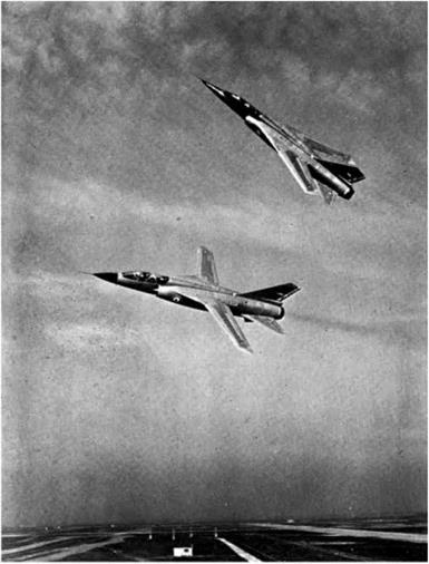
The Mirage G, with wings folded and 70° sweepback, wings extended and 20° sweepback; maximum speed in level flight Mach 2.5, landing speed 110 knots; no ailerons, lateral control (wings back) by differential action of slab tail plane supplemented when wings are spread by spoilers on wings.
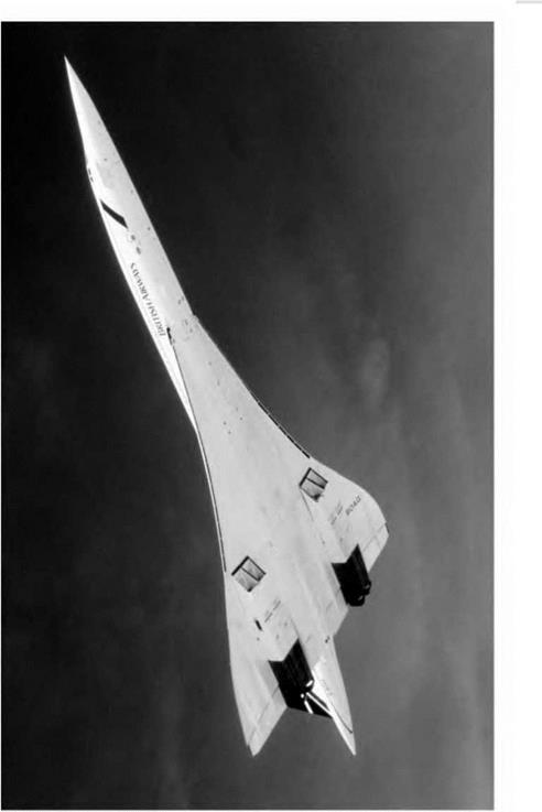
Fig 12D Concorde (opposite)
(By courtesy of the British Aircraft Corporation)
|
|
in this statement there is no reference to the shape of the wing, or where is the greatest thickness.) This value is inferior to LID ratios for subsonic wing shapes (only about half), but it is reasonably economical when everything is taken into consideration. The lift coefficient is the same for all the shapes, and although it is smaller than those of subsonic aerofoils this does not matter at high speeds; where it does matter is that it means high stalling and landing speeds, which in turn mean long runways, and devices such as tail parachutes to help reduce the speed after landing. A leading-edge flap, or a permanent droop at the leading edge (sometimes called a droop-snoot), will appreciably lower the landing and stalling speed of a supersonic aerofoil section. As with plan shape the only way of making an aerofoil suitable for subsonic, transonic, and supersonic flight is to make it variable in shape; but in this case we know that it can be done because, in fact, it has long been done – so the only question is the best way of doing it.
Figure 12.24 shows the pressure distribution, and position of the centre of pressure, for three shapes at a small angle of attack. Comment would be superfluous.


