THE LONGITUDINAL MOMENTS OF STREAMLINE BODIES
Every slender streamline body has theoretically an unstable “free” moment. Because of viscosity and the flow pattern of the type as found with slender wings, the moment is reduced, however. Therefore, in this section we will discuss the longitudinal moments including the neutral point of various types of streamline bodies. It should also be noted that in an isolated body of revolution, forces and moments due to an angle of sideslip 2?, are of the same magnitude as those due to a same-size angle of attack.
Theory. The load distribution of a slender streamline body is shown in figure 3. There are positive lifting or normal forces in the forebody and as predicted by theory, forces equal in magnitude, but directed downward (negative) in the afterbody. The corresponding free moment (no resultant force) is
М = -0.5р V2 kV sin(2oc) (15)
where к = 1, for fineness ratios-f/d above 20. The minus sign indicates in this text, that the body is unstable, that the moment tends to turn the body away from the longi – tudianl direction of the flow. “V” indicates the effective volume of the air clinging to the body, so to speak, in lateral motion. In case of a body of revolution, this volume happens to be equal to that of the solid itself. Within the range of small angles of pitch or yaw, equation 15 thus reduces to 44:
M = -2 к q V (У ; and to
0^= M/qV = —2k otradians (16)
Streamline Bodies. As indicated by theory, the free moment of streamline bodies reduces with their fineness ratio. The corresponding factor in equation 16 may be approximated by
k = (l-b/0 (17)
For ЪЦ = &Ц = 1 (suggesting the shape of a sphere) the moment thus reduces to zero.
Pressure Distribution. The pressure distribution of the ellipsoidal body in figure 22 is shown as tested along the meridian, both at the bottom (at 0°) and on the top side (at 180 ). It should be noted that the distribution as predicted by theory is symmetrical. In other words, if reversing the direction of flow, the pressure distribution of this or any other streamline body would theoretically be the same. The tested distribution agrees fairly well with theory, along the forebody. Approximately at 3A of the body length, the pressure reduction, suction, expected by theory to take place on the lower side, begins to be deficient. This means that negative circulation around the tail end is reduced. At the upper side, divergence starts roughly one diameter ahead of the maximum thickness. All along this side of the afterbody, the theoretical increase of the pressure toward a rear stagnation point, fails grossly, although both lower and upper side reach together a positive pressure level in the order of Cp = +0.1. The area enclosed between the distributions on upper and lower side is an indication for lift or normal forces. While in the forebody, the force is up, essentially as described by equation 3, the normal force in the afterbody is almost zero (at oC = 20° as tested). The consequence is a resultant lifting force, and a reduction of the unstable moment (about the point at 0.5 of the length) to roughly half the theoretical value.
![]()
![]()
 |
J
|
a – 0.5 rt
crap “ °-018 ” °-020 – 0.056 cnae – – о-009 – -0-007 ■ -0-020 |
сї4 – r/,a2 cnb – – HVqd^ j(-7.5d
Я.-сХ A— і 0Л7 Ji
Figure 23. Directional characteristics of a wing-fuselage configuration as affected by a pair of “ducts” (12,a).
Elliptical Cross Section. The volume of air affected by a streamline body when at an angle of attack or sideslip, corresponds to its thickness measured normal to the plane of angular displacement (to the “span” when at an angle of attack). For example, a fuselage body with elliptical cross section will exhibit different moments depending on whether the body is placed at an angle of attack or of sideslip. Tentatively, lift and moment will be proportional to the square of the respective “span”. Therefore, and since the volume may not always readily be known, the most appropriate moment coefficient will be:
C^M/qbV (18)
where b is meant to be the “span” or “beam” when at an angle of pitch, or the height or thickness of the body when at an angle of yaw. As stated in the beginning of this chapter, in conventional streamline bodies, the so-called block coefficient may roughly be:
“B” = У/ЦЪ h) = between 0.5 and 0.6
where b = breadth or beam and h = height. In bodies of revolution h = b = d. Referring the moment above, to the nominal volume (b2^) of the body, we obtain the coefficient
(W= M/qb2^ =
– (2^/180) к “B”o£ = -0.035 к “В” od (19)
(22) Aerodynamic characteristics of seaplane floats:
a) Liddell, Edo Floats, NACA W Rpt L-722 (1942).
b) Parkinson, Hydro – and Aerodynamic, NACA TN 656 & 716 (1938).
(23) For some reason, the neutral points in Figure 22 are less forward than those in figures 27 and 28.
EXPERIMENTAL RESULTS. In streamline bodies whose displacement volume is directly “useful” such as in airships, the center of buoyancy, tentatively identical with the center of gravity, is a convenient reference point for all moments. Moment derivatives of bare airship hulls, as tested about this point, are presented in Figure 13. The tested values are between 70 and 75% of the theoretical function using equation 19 with “B” = 6. In typical streamline bodies (with volume concentrated more forward) the theoretical pressure distribution (l, h) changes from “positive” to “negative” at the position of the maximum thickness. Thus, the corresponding point on the body axis, is the natural reference point. Experimental results of such bodies are also given in figure 13. Within the range of higher diameter/length ratios, agreement with equation 19 is obtained when using “B” between 0.30 and 0.35, instead of the geometrical block coefficient for such bodies (which is in the order of 0.5). In other words, the moments are between 0.6 and 0.7 of the theoretical function. However, at diameter/length ratios approaching zero, higher fineness ratios, experimental moments are smaller. It appears that the boundary layer along the afterbody grows with the body length, thus reducing the negative normal forces developing along the afterbody; see figures 3 and 22. In fact, we might speculate that the moment may only be half the theoretical at d// ^ zero.
“Ducts”. When adding external stores, canopies or similar, essentially “streamlined” volumes to the outside of a fuselage, the changes in normal force and moment due to angle of attack or sideslip, can be predicted or estimated using the principles and equations presented above. A pair of “ducts” (simulating the presence of jet engines, but without openings and without any flow through them) was added to a plain fuselage body (12,a). The pitch moments and the yaw moments of the configuration are presented in Chapters XI and XIII. In sideslipping motion (where the wings may be assumed not to interfere very much), the tabulation in figure 23 demonstrates:
a) With the ducts at the sides of the fuselage, the yaw derivatives remain basically unchanged. Small differentials are due to viscous interference.
b) When placing the ducts on top and below the fuselage, lateral forces and yaw moments are considerably increased.
On the basis of equation 3 and test data the lateral force increases in proportion to (h/d)2 = 1.75?=^ 3. The value of the negative, unstable, yaw moment is increased to a lesser degree, evididently because the force-producing volume of the ducts is concentrated near the CG of the configuration.
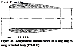 Ducted Body (15). We do not have suitable experimental results at hand, at this time, showing the influence of an axial duct upon lift and longitudinal moment of a slender body. Considering an open cylinder with unobstructed axial flow through its length, the deflection of the volume of air produces theoretically
CLo = 2tf = (‘Гґ11 SO) ot° = 0.035 ot° (20)
where the coefficient is based upon frontal area. Assuming that the turning takes place at or near the rim of the inlet, the pitch moment corresponds to the arm to the point of reference. If this point is a x = 0.5^, the maximum of the increment corresponds to the coefficient (based on body lengthy)
Сщ = – a: = -0.0175 a:° (21)
Considering a streamline body with a duct smaller than cross section, and with a-velocity through the duct lower than the ambient spped, the values above have to be reduced in proportion to velocity and area ratio. The lift differential can be appreciable (100%); the moment due to duct flow is destabilizing.
point
і
The ring wing shown in figure 24 can be considered to be a ducted slender body:
a) The unobstructed duct is expected to provide a lift component corresponding to equation 28. Based upon nominal duct area d equation 3 is obtained, dCLb/dod =0.0274.
(29) ARC, aerodynamic load distribution on airships:
a) Jones, Pressure Distribution R-33 Model, RM 801 (1922).
b) Bairstow, Aerodynamic Bending R-38, RM 794 & J’RAS July 1921.
c) Distribution on fins and rudders, RM 779,808,911 (1921).
d) Jones, Aerodynamic Loading in Turns, RM 780 (1922).
e) As reported in ARC RM 775, the airship R-38 (Zeppelin Reparation “2”) broke in two, while turning at a speed of some 50 kts. As deduced from experimen ts in (a) & (b ) lateral forces are concentrated in the bow (equation 3) and in the stem (due to fins and rudders).
b) The outside shape is that of a streamline body with cut-off rear end boat tail. Theory suggests that lifting forces on that outside correspond to equation 3.
c) The combined lift coefficient (based on the square outlet or base diameter) is theoretically
dCLb /dcx: = 2(0.0274) = 0.055 (22)
The tested value is practically the same.
Assuming that the lift derivatives of ring wings with other aspect ratios A = d/c or d/T, also tested in (21,c), also be twice that of solid bodies (having same base area) the half values of the resulting derivatives have been plotted in figure 6. Agreement with other results in that graph is excellent if doubling the fineness ratio Ц/Ъ).
(A) STREAMLINE BODIES (ENDING IN POINT)
AVA, 2 BODIES OF REVOLUTION (9,b)(ll, a)
+■ AVA "ZEPPELIN" HULL (FIGURE 45) (34)
7 NACA T/d = 6.8 AIRSHIP HULL (20,c)
Л NACA STREAMLINE BODY, J/d =6.7 (9,g)
□ BLUNT-BASED FUSELAGE, SAME AS IN – T (B)
О RECANT, PLAIN FUSELAGE, J/d =5.9 (9,e)
• TH MU ROUGH BODY AS IN FIGURE 4 (9,c)
(B) BLUNT-BASED "FUSELAGES"
□ TN 3551, "PARABOLIC" SQUARE FUSELAGE (10,e) Q TN 3551, "PARABOLIC" ROUND BODY (10,e)
• BODY WITH SURFACE ROUGHNESS AS IN(A) (9,c)
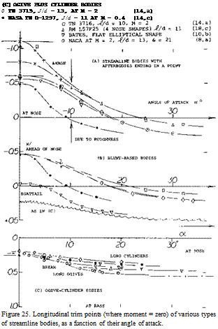 V NACA "PARABOLIC" BODY WITH BOATTAIL (17,e)
Neutral Point. The ideal moment of streamline bodies (without any resultant force) is “free” (independent of the point of reference). Since in real, viscous fluid flow, every body does develop lift (or a lateral force) when at an angle of attack (or of yaw) the longitudinal moment depends upon the axis of reference. To say it in different words, the resultant force produces a moment about the center of gravity or whatever axis is used. The location of the resultant force can only be obtained from pressure distribution tests, as for example in figure 3. Usually, therefore, its moment contribution is not known.. Another method of describing the combined moment, is to quote the point on the axis of the body, for which the combined moment is zero. For small angles of attack (where both lift and moment vary in linear proportion) the moment reduces to zero at the neutral point, the location of which is away from the axis about which the moment was tested, by
A xty = dCM/dCL = (dCyry/dot )/(dCL /da;) (23)
For example, the neutral point of the bare airship hull in figure 21, is approximately at x = —ahead of the body’s nose.
lift
Zero Moment. The location x for the zero moment is determined by
A x/f C^/Q. (24)
In such points, the body is in trimmed condition, which does not mean that it would be stable. The point for zero moment changes in the manner as shown in figure 25. The most forward location of every particular body is around zero angle of attack, as defined by equation 23. In “typical” streamline bodies (with a tail tapering to a point) the neutral point is far ahead of the nose. As the angle of attack is increased, the point moves back, it reaches the body nose at angles around 20 . Depending upon the location of maximum thickness, the point may then approach a position between lA and Й the length of the body.
Cylindrical Streamline Bodies. An ogival or conical streamline body can be expected to produce the circulation-type linear lift component. This lift force acts within the length of the nose shape. Characteristics of one such body are presented in figure 26. As the second, non-linear normal-force component develops, the center of the combined force will move downstream. If the linear lift component is located at 0.4 of the nose length, and the cross-flow component assumed to be centered at lA the length of the cylindrical afterbody, the combined center of pressure is found to be as tested, for example near 50% of the length at angles of attack between 16 and 20 .
 Nose Shape. Results of a cylindrical body are presented in figure 14, for several shapes of the forebody:
a) As soon as a small rounding radius is provided (as small as 10% of the diameter) the drag coefficient CDo drops from 0.9 to less than 0.2.
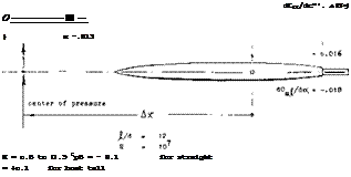
Comparison of a pair of streamline bodies (18,a) as to their stability derivative Ax/( =(dCmb2^/doc)/(dCLb/doO, taken within the range of Ы = +— 8°, or CLb = +- o.15.
Figure 26. Influence of afterbody shape on the longitudinal (or directional) characteristics of a fuselage body.
(30) Aerodynamic characteristics of airships:
a) Klemperer, Stalling, J Aeron Sci 1934 p 113.
b) Freeman, “Akron” Pressure Distribution, NACA T Rpt 443.
c) Frazer, “Full Scale Experiments”, J. RAS Sept 1925.
d) References appended to Jones, J RAS Feb 1924.
e) Rizzo, Static Stability, NACA TN 204 (1924).
f) Arnstein and Klemperer, Aerodynamics and Stability of Airships, see Durand’s “Aerodynamic Theory”, Volume VI.
b) The normal-force derivative is roughly independent of nose shape. The experimental values are slightly higher than the dC^ /doc = 0.0274 as indicated by equation 3; see equation 8.
c) Disregarding the really blunt shape, the pitch moment derivative is approximately independent of nose shape. On the average, the aerodynamic center is at
A x/j = dC^/dC^ = 0.012/0.030 = 0.4
ahead of the reference point. In other words, the center of lift within the range of small angles of attack (say to plus/minus 4°) is at x/.( = 0.57 -0.40 = 0.17, or at x/d = 1.6, behind the nose point.
Afterbody. The experimental results in figure 15 give a perfect illustration of slender body aerodynamics:
a) the ogival forebody produces the theoretically expected lateral force (equation 3).
b) a cylindrical afterbody may produce a small component of force, of the type as described in context with equation 8.
c) a boat-tailed afterbody produces a negative component of lift, in the manner if not magnitude, as predicted by theory.
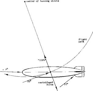
Curvature. An airship or a submarine when turning, moves into a curved stream. As illustrated in figure 28, geometric conditions may then be such that nose and forebody are at an angle of yaw close to zero, while at the stern and the tail fins, the angle is in the order of 37°. This condition can roughly be simulated by testing a curved or cambered body in a straight stream of air or water. There are also bodies which are cambered naturally, such as the float in figure 25, or certain fuselages.
 Cylindrical Middle Body. There are streamline shapes such as possibly in airship hulls or fuselages, where a considerable part of the length is cylindrical. Basic theory expects destabilizing lifting or normal forces to originate in the bow and the stern, while the cylindrical middle body is not supposed to contribute to force or moment as far as small angles against the wind are concerned. Since the bow and stern have a considerable moment (about the center of buoyance or the CG) such partly cylindrical bodies may have larger moments than truly streamline shapes (with the same fineness ratio).
Cross Section. A series of four “fuselages” differing in the shape of their cross section are reported in 14,a. As shown in Figure 12 of Chapter XI, the lift and pitch moment essentially a function of the body width. A fuselage with a flat and wide shape has considerably larger pitch moments, accordingly, while a “deep” and naroow body has reduced moments, defined about the point at x/^ = 0.54. As series of 4 blunt-based bodies is presented in figure 12, differing in the span/thickness ratio of their cross sections. The pitch moment about the point at x = 0.58^ , properly referred to b2 and^ , reduces from 0.007 to 0.003, as the span ratio is increased to 3. The neutral point moves downstream from хЦ = —0.8 (ahead of the body’s nose, for the body of revolution) to хЦ – +0.2 for b/t = 3.
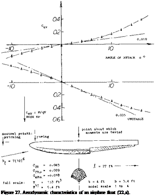
Seaplane Float. Not all streamline bodies are rotationally or otherwise symmetrical. Aerodynamic characteristics of a float are presented in figure 27. Lift and moment seem to vary in the same manner as in other bodies. There is an irregularity, however, in the moment function, within the range of negative angles of attack. It is suggested that the flow separates here from the bottom of the float, behind the step.
Camber. Characteristics of a cambered body are presented in figure 29. For the linear circulation type of lift, the zero angle of attack corresponds to the tangent at about 3A of the forebody length (near the point where the forebody lift may be centered). The slope is the same as that for the straight body. For the non-linear lift component, the average angle of attack of the afterbody can be expected to be responsible. This angle is (a: + A oc) and the non-linear normal-force component may be
(ot + A oC)Z

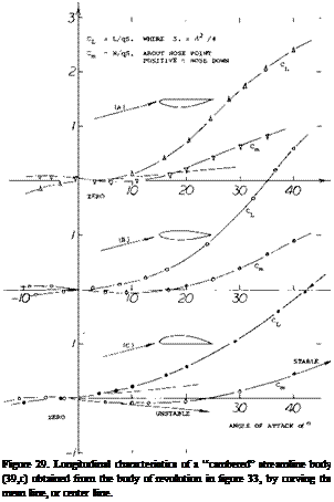
![]() In the body as in figure 29, camber is “с”Ц&&0.5 djj( = 0.5/5.8 = 0.086. This ratio can be understood to be an angle equal to 5°; id est 0.086 (180/^гґ) « 5°. The non-linear lift component as tested, can be explained by
In the body as in figure 29, camber is “с”Ц&&0.5 djj( = 0.5/5.8 = 0.086. This ratio can be understood to be an angle equal to 5°; id est 0.086 (180/^гґ) « 5°. The non-linear lift component as tested, can be explained by
Z CL (o’ -3° + 4°)Z
where 3° = zero-lift angle of attack, and 4° = similar to the 5 corresponding to camber. For example, at o~ = 19 —3 +4 = 20 (as in part C of the graph), the non-linear component is approximately the same as at oC = —19 —3 +4 = —18° (as plotted in the form of +18° in part A of the graph).
|
Figure 28. Geometry and lateral forces of an airship (or of a submarine) during a turn. Dimensions are assumed in such a manner that the stream curvature corresponds to the camber of the body in figure 29. |
(31) Characteristics of airship fins:
a) ARC, Model Results, RM 714, 799, 802, 1168.
b) NACA, Technical Reports 215, 394, 432.
c) Pressure distributions, ARC RM 808, 811, 1169.
d) Pressure distributions, NACA T Rpts 213, 324, 443.


