Unsteady 2D Airfoil
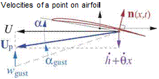
The unsteady 2D airfoil problem is important in many applications, such as prediction of gust loads on wings, cyclic loads on rotor blades, and the onset of flutter. See Bisplinghoff et al [53] for an overview. Here we will consider the case of a rigid airfoil moving at a uniform horizontal speed U, while undergoing unsteady heaving h(t) and pitching O(t) displacements about a baseline position and angle of attack a0, as shown in Figure 7.8. Note that the heave displacement h is defined positive down.
camberline Z(x) —, Midchord
" reference point

 ao ‘
ao ‘
U x
![]() Inerti
Inerti
Figure 7.8: Airfoil moving at uniform horizontal baseline velocity U. Heave and pitch displacements h(t), 6(t) from baseline position give net resultant vertical velocity h + Ox at a some point x, which then define the local angle of attack a(x, t). Some vertical gust velocity wgust(t) produces an additional angle of attack agust.
3.1.5 Geometric relations
The assumptions of first-order thin airfoil theory will be employed here. The airfoil camberline shape is Z(x), with a negligibly small thickness. The geometric and flow angles are assumed to be small.
Z’ < 1 , ao, O < 1 , h, Oc, Wgust < U
Following historical convention for unsteady airfoil analysis, the airfoil extends over —c/2 < x < c/2, so the reference point x = 0 is at midchord, as shown in Figure 7.8.
3.1.6 Problem formulation
The problem will be formulated in the frame and the axes of the inertial Earth-based observer. The camberline’s normal vector therefore rotates with the airfoil.
The small-angle assumptions give the following total velocity of a point on the airfoil.
![]() Up(x, t) = — U x — (h + Ox) z
Up(x, t) = — U x — (h + Ox) z
The perturbation velocity field is represented by a vortex sheet of strength 7(x) on the airfoil and wake. The wake portion is absent in steady thin airfoil theory (Appendix D), but is needed here to represent shed vorticity. In the Earth frame, the total vortex sheet strength gives the following instantaneous vertical fluid velocity w at any given location on the x-axis, which adds to any wgust already present.
In the airfoil frame, the corresponding fluid velocity at location x is then
Vrei = (w + Wgust) z — Up = U x+ h + Ox + w + WgustJ z (7.40)
which is then used in the usual flow tangency condition on the camberline.
Vrel ■ n = 0 (—c/2 < x < c/2) (7.41)
This applies only on the airfoil. In the wake, we must instead impose the zero pressure jump condition, by taking the x-derivative of the Др convection equation (7.22), which then becomes the y convection equation. The governing equations over the entire vortex sheet —c/2 < x< to are then stated as follows.

![]() = Ua0 — UZ’ + h + (UO + Ox) + wgust (—c/2 < x < c/2) (7.42)
= Ua0 — UZ’ + h + (UO + Ox) + wgust (—c/2 < x < c/2) (7.42)
= 0 ( c/2 < x < to ) (7.43)
 |
|
The pressure loading required to calculate the lift and moment is obtained from equation (7.21). This in turn requires the time rate of the potential jump, which is defined in terms of the vortex sheet strength time rate.
Because equations (7.42) and (7.43) are both linear in y, their solution y(x, t) and corresponding Др^у) and Др^у) can be decomposed into five independent components, with each component determined entirely by one of the five righthand side source terms in (7.42).
Y(x, t) = Ya(x) + Yz (x) + Yh(x, t) + Ye(x, t) + Ygust(x, t) (7.46)
The first two contributions Y«,YZ are steady since they depend only on the fixed baseline angle of attack a0 and camberline shape Z(x), respectively. These are treated by standard steady first-order thin airfoil theory, as derived in Appendix D. This result for the steady case is
![]() Q = c£o + 2nao
Q = c£o + 2nao
cmc/4 = cmo
where ci0 and cmo depend only on the camberline shape. In the subsequent sections we will ignore these steady contributions and focus only on the three remaining unsteady parts driven by h(t), O(t), wgust(t) which determine Yh, Ye, Ygust, respectively, and also their corresponding unsteady lift and moment.


