Boundary layer control for the prevention of separation
Many of the widely used techniques have already been described in Section 8.3. But there are various other methods of flow-separation control that are used on aircraft and in other engineering applications. These are described here.[64] Some of the devices used are active, i. e. they require the expenditure of additional power from the propulsion units; others are passive and require no additional power. As a general rule, however, the passive devices usually lead to increased drag at cruise when they are not required. The active techniques are discussed first.
8.4.1 Boundary-layer suction
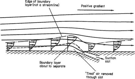
The basic principle was demonstrated experimentally in Prandtl’s paper that introduced the boundary-layer concept to the world.* He showed that the suction through a slot could be used to prevent flow separation from the surface of a cylinder. The basic principle is illustrated in Fig. 8.22. The layer of low-energy (‘tired’) air near the surface approaching the separation point is removed through a suction slot.
|
Fig. 8.22 |
The result is a much thinner, more vigorous, boundary layer that is able to progress further along the surface against the adverse pressure gradient without separating.
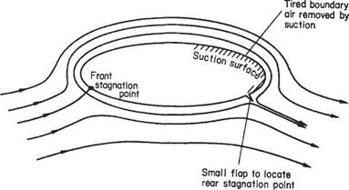
Suction can be used to suppress separation at high angles of incidence, thereby obtaining very high lift coefficients. In such applications the trailing edge may be permitted to have an appreciable radius instead of being sharp. The circulation is then adjusted by means of a small spanwise flap, as depicted in Fig. 8.23. If sufficient boundary layer is removed by suction, then a flow regime, that is virtually a potential flow, may be set up and, on the basis of the Kutta-Zhukovsky hypothesis, the sharp – edged flap will locate the rear stagnation point. In this way aerofoils with elliptic, or even circular, cross-sections can generate very high-lift coefficients.
|
|
Fig. 8.23
|
bleed holes Fig. 8.24 Features of the F-15 engine-inlet flow management |
There are great practical disadvantages for this type of high-lift device. First of all it is very vulnerable to dust blocking the suction slots. Secondly, it is entirely reliant on the necessary engine power being available for suction. Either blockage or engine failure would lead to catastrophic failure. For these reasons suction has not been used in this way for separation control in production aircraft. But it has been tested on rotors in prototype helicopters.
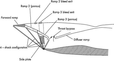
Many supersonic aircraft feature forms of suction in the intakes to their engines in order to counter the effects of shock-wave/boundary-layer interaction. Without such measures the boundary layers in the inlets would certainly thicken and be likely to separate. And some form of shock-wave system is indispensible because the air needs to be slowed down from the supersonic flight speed to about a Mach number of 0.4 at entry to the compressor. Two commonly used methods of implementing boundary- layer suction (or bleed) are porous surfaces and a throat slot by-pass. Both were used for the first time in a production aircraft on the McDonnell Douglas F-4 Phantom. Another example is the wide slot at the throat that acts as an effective and sophisticated form of boundary-layer bleed on the Concorde, thereby making the intake tolerant of changes in engine demand or the amount of bleed. The McDonnell Douglas F-15 Eagle also incorporates a variety of such boundary-layer control methods, as illustrated in Fig. 8.24. This aircraft has porous areas on the second and third engine-inlet ramps, plus a throat by-pass in the form of a slot and a porous region on the sideplates in the vicinity of the terminal shock wave. All the porous areas together account for about 30% of the boundary-layer removal with the throat by-pass accounting for the remainder.


