Heliocentric and inertial coordinate systems
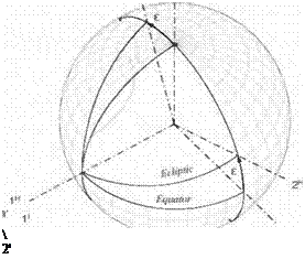
3.2.2.1 Go back and review Figs. 3.4 and 3.5. We choose the preferred coordinate system of the inertial frame triad i, i2, and І3 (see Fig. 3.12). The Iі inertial axis is aligned with the
 |
з1
vernal equinox, and the 31 axis with the north pole. The I’ and 21 axes lie in the equator. The heliocentric coordinate axes are tilted by the obliquity of the ecliptic є. Let us build the TM [T]HI of the heliocentric wrt the inertial coordinate systems with the help of Eq. (3.5)
[hxV
 1Ы1
1Ы1
VhY
where the [hi]1, і = 1, 2, Зате the base vectors ofthe heliocentric triad coordinated in inertial axes. By inspection of Fig. 3.12, you should be able to verify
 (3.11)
Notice the pattern of the TM. The 1 appears in the first column and row indicating that the transformation is taking place about the 1 direction without change in coordinates. The diagonals are the cosine of the transformation angle, a fact verified from the direction cosine matrix Eq. (3.6). The remaining off-diagonal elements are the sine of the angle, again verifiable by Eq. (3.6). You only have to decide where to put the negative sign. A simple rule says that the negative sign appears before that sine function, which is above the row containing the 1. If that row is on top, as in our example, imagine continuing rows in the sequence 3-2-1.
An alternate rule focuses on the positive sign. Inspect Fig. 3.12. The new axis that lies between the original axes indicates the row with the positive sine function. In our case 2H lies between 21 and 31; therefore, the second row of the matrix carries the positive sine.
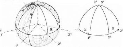
As promised, I peel off the connections between the piercing points and have drawn them in Fig. 3.13. To help you in the transition, I still show the coordinate axes. With practice you can soon do without them.
 |
By earlier agreement we use only right-handed coordinate transformations. Transforming the ]’ system about the 1′ axis, we bring the 21 axis through the angle £ to establish the 2H axis by a right-handed motion with the index finger
3′ 3E
l
|
pointing in the I’ direction. This transformation [T]HI is symbolically expressed as ]H verbahzing transformation of coordinate system H wrt I through
the angle є. Sometimes I may also use the expression, “transforming from I to H through the angle є” although the first form is preferred. Taking the transpose of the TM [f]H/ changes the sequence of transformation to [T]m, through the negative angle —є, or symbolically ‘ <— ]я.


