Impinging Jet Heat Transfer
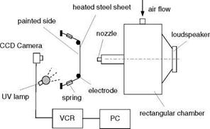
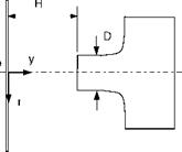
Using TSP complemented with hot-wire sensors and smoke visualization technique, Liu and Sullivan (1996) studied the relationship between heat transfer and flow structures in an acoustically excited impinging jet. Figure 10.14 is a schematic of a variable-speed air jet facility and the coordinate system. The facility consisted of two settling chambers. Air from a motor-driven centrifugal blower entered the first rectangular settling chamber (254x533x483 mm) and then passed through the second chamber that actually was a 178-mm long cylinder tube of a 48 mm diameter. A 25-mm long contoured nozzle was mounted at the end of the tube. The nozzle exit diameter D was 12.7 mm and the contraction ratio was
5.2. A loudspeaker attached to the opposite side of the first chamber to the nozzle induced organ-pipe resonance in the chamber, producing axisymmetric and plane – wave excitation at the jet exit. To measure the local convection heat transfer coefficient, air jet impinged on a 0.0254-mm thick, 115-mm wide and 130-mm long stainless steel sheet that was heated by passing an electric current of 25
Amperes. The sheet was stretched tautly by springs over two 12.5-mm diameter aluminum rods that also served as electrodes, and deformation of the sheet due to jet impingement was negligibly small. Given the uniform heat flux Qs from the heated sheet surface and the measured surface temperature Ts of the heated sheet, the convection heat transfer coefficient h = Qs/(Ts – T^ ) and the Nusselt number Nu = hD/k were calculated, where T^ was the ambient temperature and к was the thermal conductivity of air.
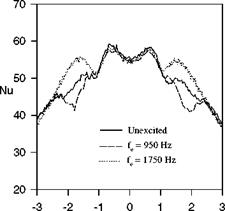
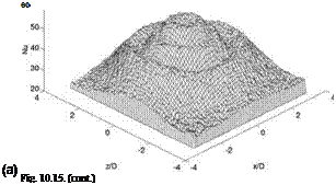
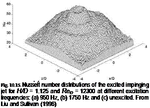
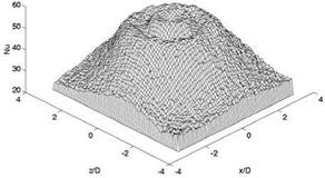
To measure the surface temperature Ts, EuTTA-dope TSP (about 10 |jm thick) was coated on a 0.05-mm thick white Mylar film attached on the backside (relative to the jet impingement side) of the stainless steel sheet. A UV lamp was used to illuminate TSP. The luminescent intensity images were taken by a CCD viedo camera and digitized using a frame grabber with a spatial resolution of 512×512 pixels. The monochromatic excitation affected flow structures and therefore changed the heat transfer rate on the impingement surface. Figure 10.15 shows the 2D Nusselt number (Nu) distributions of the impinging jet at the excitation frequencies 950 Hz and 1750 Hz and without excitation for H/D = 1.125 and ReD = 12300. The natural frequency of the jet was 1750 Hz and the subharmonic frequency was 950 Hz. Clearly, the 2D heat transfer distribution was sensitive to the excitation frequency particularly in the wall-jet region. The transverse heat transfer distributions in the excited impinging jet for H/D = 1.125 are shown in Fig. 10.16, compared to the unexcited impinging jet. At the natural frequency of 1750 Hz, the local heat transfer coefficient in the wall-jet region (1< r/D <2) was considerably enhanced by excitation compared to the unexcited impinging jet. In contrast, at the subharmonic frequency of 950 Hz, the local heat transfer coefficient was reduced in the wall-jet region. Near the stagnation-point flow region (-1< r/D <1), the monochromatic excitation did not significantly affect the time-averaged heat transfer coefficient. In the wall-jet region, the heat transfer enhancement or reduction by excitation was related to the development of the large-scale vortical structures that were studied using smoke flow visualization coupled with hot-wire and hot-film measurements. When the excitation frequency was close to the natural frequency of the impinging jet, intermittent vortex pairing occurred, producing chaotic ‘lump eddies’ that contained a great deal of small – scale random turbulence. The random vortical structures enhanced the local heat transfer. When the forcing was near the subharmonic of the natural frequency, stable vortex pairing was promoted; resulting strong large-scale well-organized vortices induced unsteady separation of the boundary layer in the wall-jet region and caused a reduction in the local heat transfer coefficient. This experimental study demonstrated that TSP, complemented with other experimental techniques, provided an effective tool for study of basic fluid mechanics and heat transfer problems.
![]()
|
|
|
|
|
|
|
|
 |
![]()
|
|
 |
|
|
r/D
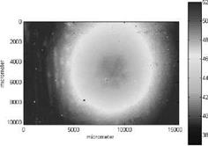
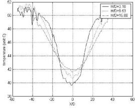
Using EuTTA-dope TSP, through an optical microscope and a close-up lens attached with a cCd camera, Huang et al. (2002) measured the surface temperature distributions in impinging micro-jets. The tested micro-jets were a single jet of a 200-pm diameter, a multi-jet with 19 holes of a 200-pm diameter, and a multi-jet with 19 tubes of a 100-pm inner diameter. The experimental setup arrangement of micro-jet impingement was similar to that used by Liu and Sullivan (1996). Figure 10.17 shows a typical temperature map in the impinging multi-jet with 19 holes of a 200-pm diameter for H/D = 19.05, where the Reynolds number based on the diameter was about 300. Figure 10.18 shows the temperature distributions along the centerline of the multi-jet for three impingement distances from the surface.
|
Fig. 10.17. Surface temperature distribution of the impinging multiple-micro-jet at H/D = 19.05. From Huang et al. (2002) |
|
Fig. 10.18. Surface temperature distributions along the centerline of the multiple-micro-jet at three impingement distances. From Huang et al. (2002) |


