INTERRUPTIONS OF SPAN
In the practical design of an airplane the need for data on the physical interruptions of the span may be encountered. This is particularly true in the application of all movable surfaces, such as might be encountered with tilt wing aircraft or the structural mode control fin illustrated on figure 33.
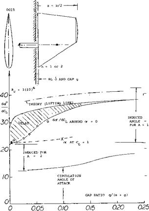
With Longitudinal Gap. Really cutting a wing in two eventually means reducing its aspect ratio to one half. The effective ratio decreases as a function of the gap between the two halves of such a wing. Theory (22,a), considering two lifting lines (having no physical chord), expects a rapid decrease of At /А. Experimental results (22,b) of a rectangular wing (presented in Chapter VII of “Fluid Dynamic Drag”) show, however, that chord and thickness of the square and blunt wing ends are obstructions for the flow through the gap, at least for ratios of y/b below 0.03, or y/c = 0.2. The induced characteristics of a pair of wings or airplanes flying side by side can be derived from this information. A real gap is found between an all-movable control surface (fin or rudder, as on submarines in particular) and the adjoining “wall” of the vehicle.
|
|
|
|
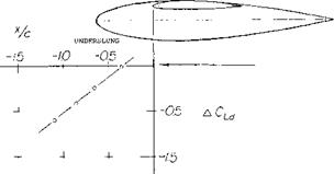
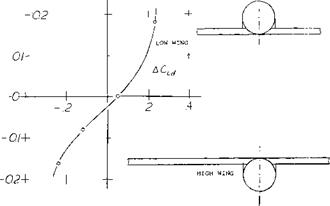
Figure 32. Influence of vertical position of a wing nacelle body combination on the lift.
Theoretically, the aspect ratio of the fin as in figure 33 is doubled through reflection in the wall. The lift angle, however, increases as the gap is opened from that for A = 2 to that corresponding to an A = 1. The increase is steady but not at all as sudden as theory (permitting infinitely high velocities without losses) would expect. It should be noted that in reality (as for instance at the end of a fuselage) the boundary layer can be appreciably thicker than that found on the wall of the wind tunnel in which the rudder, as in figure 33, was tested.
|
|
Figure 33. Influence of a wall gap upon the lift angle of a control surface.
(20) Pearson and Anderson, Wings with Partial-span Flaps, NACA Tech Rpt 665 (1939).
(21) Characteristics of wings with cutouts:
a) Ergebnisse AVA Gottingen Vol. Ill (1928) p 92.
b) Muttray, 2’ts Flugtechnik Motorluft 1929 p 161.
c) Sherman, Cut-Outs, NACA Г Rpt 480 (1934).
d) Smith, Wing Cut-Outs, NACA T’Rpt 266 (1927).

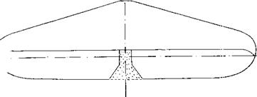
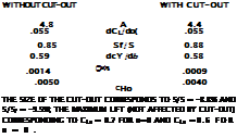
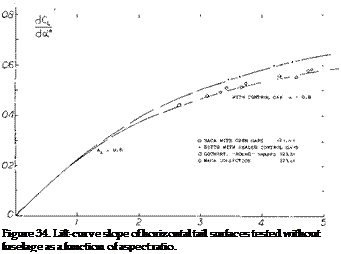 Horizontal Tail Surfaces are an example of “wings” with moderate aspect ratio. The type, as in figure 34, has a more or less rounded planform, has a cut-out for the rudder, and has gaps to permit deflection of the elevator. The effective aspect ratio as well as the section efficiency are reduced, accordingly. Regarding cut-outs, the experiments reported in (23,a) do not show any influence upon the lift curve slope, provided that the lift is referred to the reduced area. The lift-curve slope of typical horizontal surfaces are plotted in figure 34. The difference between the tail surfaces and the “round” wings, figure 2, Chapter III, can be accounted for by reducing a from 0.9 to 0.8. This difference is primarily due to the open gaps along the hinge lines of the elevator flaps. In comparison to sharp-edged and rectangular wings the lift-curve slope is appreciably reduced, roughly between 16 and 19%.
Influence of Fuselage. When testing a half wing at the wall of a wind tunnel or mounted on a suitable end plate, the boundary layer developing along the wall can noticeably reduce the lift of that wing. In combination with an adverse pressure gradient, boundary-layer interference is particularly strong at the end of a fuselage. The B’ layer developing reaches such proportions that at the location of the tail surfaces it fills a circle roughly equal in diameter to that of the fuselage. As pointed out in Chapter VIII of “Fluid Dynamic Drag”, the horizontal tail is thus cut in half, so to speak; and its induced drag can be doubled. The lift of the combination reported in (16,b) is shown in figure 2 of Chapter III. The lift deficiency is largest at small angles of attack, where the lift-curve slope is but 11% of that of the isolated tail surface. At some angle of attack corresponding to CL = 0.7, the maximum value of (C Jot) is still 11% below the isolated slope. As indicated in “Fluid Dynamic Drag” the effective aspect ratio reduces according to
А(УА = 1 – 12 Срн (25)
where the coefficient represents the fuselage drag (including everything attached to it and wing-root interference) and is referied to the total planform area of the tail surface (subscript H).
|
|
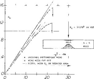
Figure 35. Lit characteristics of a wing with faired cutouts. Coefficient based on the original wing area.
![]()
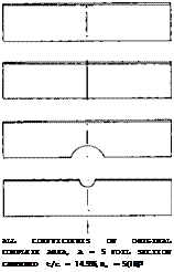 Cutouts. Figure 35 presents the influence of a well profiled cutout as it was used many years ago in the upper wings of biplanes (to give the pilot a better view). Disregarding lift coefficients above 0.9, the effect is that of lift distribution (with a dent in the center). Some possible reductions in chord in the center of a wing are shown in figure 36. Because of flow separation the leading edge is more sensitive than the trailing edge. A lot of lift can also be lost, however, on account of a cutout from the rear. While the reduction of wing area in part (c) of the illustration is only 8%, that of the lift is 15%. Analysis shows that the effective aspect ratio is reduced to 82%. Any disturbance of the high-speed flow along the upper side of the wing roots may thus produce the equivalent of a gap or cutout in the wing span. In fact, cutouts have sometimes been used at the trailing ends of the wing roots to reduce downwash and improve longitudinal stability.
dc* /dcL dcD/dc2L


