LIFT OF WING-BODY COMBINATIONS
When a wing fuselage and/or engine nacelle are combined the lift of the combination is different than would be found by summing the lift of each body alone. The difference in the total lift is a result of the mutual interference due to the flow fields of each body. Until recently the mutual interference effects of wing-body combinations could only be determined by test. With the development of the vortex lattice technique, progress has been made in calculating the lift of the combination (15,g).
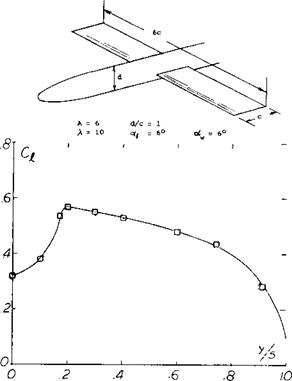
Alpha Flow. The interference of wing-body combinations can be determined by considering a circular cylinder inclined at some small angle of attack. At this condition then a component of the flow corresponding to (V sinof ) crosses the cylinder. This component is zero at the windward “stagnation” line of the body. At least theoretically, it reaches the maximum value of (2V sinof ) at the sides of the cylinder. As a result, the angle of the flow relative to the body axis is doubled. Placing now a wing across the cylinder, its angle of attack at the roots is equal to “2 ex’ ”. This type of upwash is illustrated in figure 6, Chapter XIX. The resultant lift distribution of a mid-wing fuselage configuration is shown in figure 28. At the roots a pair of peaks is evident.
Body Lift. Circulation and pressure distribution around the roots of a wing are transferred to a certain degree upon the fuselage. To understand this phenomenon, we may consider the two wing panels to be end plates prohibiting any flow around the sides of the body (at least within the length of the root chord). For example, in the configuration as in figure 28 the aspect ratio of the center part of the wing covered by the fuselage is A0 = d/c =
1.0. The “height” of the “end plates” each is ‘h’/d = 3.0. According to the function presented in Chapter III, the effective aspect ratio of the fuselage is then Ac = 5.7A = 5.7. The coefficient of the lift on area (dc) induced upon the body by the wing is then 95% of the average of the wing panels. A more accurate analysis is presented in (15,d). The lift induced by a wing rotated to an angle of attack against a long cylindrical fuselage with d = 0.36 c, kept at zero angle of attack, is indicated by the differential based on area (dc):
zlCLcj – kCL (14)
where CL = average lift coefficient in the panels of the two-dimensional rectangular wing, and к is a constant to be discussed in the next paragraph. At any rate, the lift is less in this case than that of the wing alone. A situation similar to this one is obtained when deflecting trailing – edge wing flaps, such as in (16,c) for example.

![]()
(14) Airplanes using tandem wings, as the once-famous French “Pou du Ciel” (“Sky Flea”), were more a combination of biplane and tandem system.
(15) Analysis of the lift of wing-body combinations:
a) Multhopp, Alpha Flow, Lufo 1941; NACA TM 1036.
b) See NACA RM A1951G24, L1951J19, L1952J27a.
c) Weber, Spanwise Loading, ARC RM 2872 (1956).
d) Cross Flow, see also “slender body” chapter.
e) Hoerner, T’Rpt F-TR-1187-ND WP AFB (1948).
f) Vladen, Fuselage and Engine Nacelles Effects on Airplane Wing, NACA TM 736.
g) Ashley, Wing-body Aerodynamic Interaction, Annual Review of Fluid Mechanics, Vol. 4, 1972, p 431.
h) Flax, Simplification of the Wing-Body Problem, J of A, Oct. 1973.
i) Mendenhall, Vortex Shedding on Aero Characteristics of Wing-Body Tail, NASA CR-2473,1975.
(16) Wing-body combinations, experimental:
a) Jacobs, 209 Combinations, NACA T’Rpt 540 (1935).
b) Sherrnan, 28 Combinations, NACA T’Rpt 575 (1936).
c) Sherman, With Split Flaps, NACA TN 640 (1938).
d) Gimmler, Pressure Distribution on Wing-fuselage Combination, German ZWB FB 1710 (1942).
e) Goodman, Wing-body Position with reference to interference NACA TN 2504.
Wing With Body. When rotating wing and fuselage together the lift induced on the body, aCLcj corresponds to
AC[_d = 2kCj_ (15)
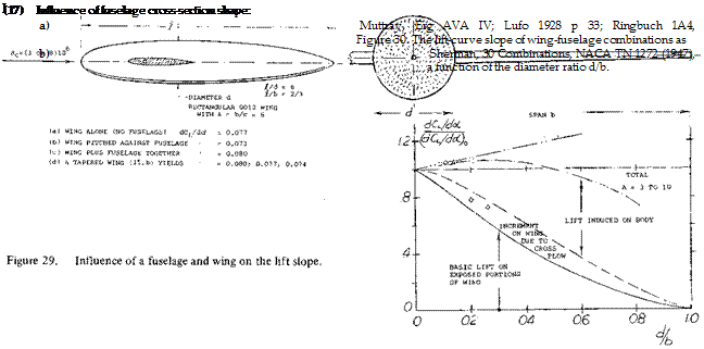
where к – 0.2. However, considering a wing with conventional aspect ratio and possibly elliptical lift distribution, the proper factor might be к = (4/тГ)0.2 = 0.25. At least the same amount of lift is added to that of the wing panels so that the combined lift is somewhat increased. For example, in the combination as in figure 29 where d/b = 0.1, the increment is in the order of 4%. Figure 30 shows the increase of total lift as a function of the diameter/span ratio. As derived in (15,f) the three components of lift in larger aspect ratios are approximately as follows:
the lift increment of the exposed portions of the wing
LV =L^B (1-о)5/з (16)
due to cross flow or alpha flow
L„ = L^B cr(l-o/3 (17)
lift induced on the body by the wing
LB =LwB <г(1+а)(1-<т)2/з (18)
where о is the body diameter d over the full span b, cr = d/b and is the lift of the complete body system. The interference effects of the wing and body have also been given in (15 ,g) as
LwB=Lw- 0 +0-)2– Total lift @CX (19)
= L*r (1 + cr) – – Lift wing alone (20)
L B = L*. <r (1 + cr) – – Body lift (21)
The lift given in equations 19 and 20 include the interference effects.
For small (d/b) ratios we find approximately
(dcL /dor)/(dCL Ida) =1+0.2 (d/b) (22)
Fuselage Shape. Not all fuselages are circular in cross section. Shapes as in figure 7, Chapter XI have been investigated. In general it can be said that bodies with a more or less flat bottom, adjoining the wing roots, tend to produce higher lift-curve slopes. Minimum drag and drag due to lift of such shapes are not necessarily higher than for the circular cross section.

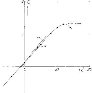
WEBER EXPERIMENTAL A = 3 AND = 10 (15,C) JUNKERS, RECTANG LOW WING A = 6,SEE(15,e) NACA, RECTANGULAR MID WING A = 6 (16,a) NACA, WING COMPONENT (MAYER-GILLIS)
![]() HIGH WING
HIGH WING
LOW WING POSITION
|
|
Figure 31. Lift differentials caused by typical high – and low- wing engine nacelle bodies.
Displacement. A fuselage or an engine nacelle displaces the flow around it (perturbation). This effect becomes particularly evident in high-wing or low-wing combinations. To explain the consequences of displacement, we may assume that in one strip of an airfoil the velocity may be reduced 50% and in another strip increased 50%. While the average velocity thus remains constant, the average of the dynamic pressure is now 0.5 (0.52 + 1.52) = 1.23 times that of the undisturbed flow. A pair of round nacelle bodies (with a length І = 1.5 c) are shown in figure 31. For practical purposes the lift-curve slope remains unchanged. However, the low-wing type (with the nacelle above the wing) exhibits an increment of the lift coefficient, based on the covered area (d c), of AC|_ = + 0.18 while the underslung nacelle shows a differential of – 0.17. The signs of these differentials can be explained by displacement, as above. In regard to drag, it should be noted that the low-wing configuration evidently suffers from interference along the roots (on the upper side of the wing).
Engine Nacelles. The wing position on the streamline body as in figure 32 was systematically varied. In an underslung forward position (with the body nose at x/q 100% of the wing chord ahead of the leading edge) a displacement Tow develops, resulting in ACLd = – 0.5. For x/c = – 30% (aft position investigated) the lift coefficient is not affected. As a function of height (low wing and high wing), ACtd varies as shown in the illustration.
![]()
Fillets. Of course, viscosity (skin friction, boundary layer, flow separation) reduced any peak in the lift distribution which may theoretically be predicted for the wing roots. Fillets used to fill out the corners between the upper side of the wing roots and the fuselage walls (18,a) are only effective when extending downstream, somewhat beyond the trailing edge. Their benefits are found at higher angles of attack and in the maximum lift coefficient. A disadvantage of fillets can be increased down wash and reduced longitudinal stability. Bending up the trailing ends of the root sections is a possible method of reducing downwash without causing separation.
Induced Drag. The influence of the angular setting of the nacelle against the wing chord results in dCLd /di = 0.036. At least half of this lift originates on the wing panels. As pointed out in Chapter VIII of “Fluid-Dynamic Drag”, a certain amount of induced drag results from any lift differential. In the low-wing or high-wing position, as in figure 31, the induced component of the nacelle corresponds to C D<k = 0.01, while the total drag (body, interference, induced) is in the order of = 0.04. It is suggested that the variations of the forces are similar to those due to the deflection of a trailing-edge flap over a part of the span equal to the diameter of the body, as described in (22). This approach accounts for constant differentials of lift and induced drag.
(18) Wing-fuselage junctures (fillets):
a) Sherman, NACA TN 641 & 642, T’Rpt 678 (1939).
b) Muttray, see NACA TM 517 and 764 (1935).
(19) Influence of engine nacelles on lift:
a) McLellan, Nacelle Position, NACA TN 1593 (1948).
b) Becker, Twin-engine Model NACA T’Rpt 750 (1942).
c) Pepper, Fuel Tanks, NACA W’Rpt L-371 (1942).


