Linear-Strength Vortex Method
The constant strength vortex method of Section 11.2.3 posed some difficulties which can be corrected by using the linear strength vortex element. To describe the method let us follow the basic six step procedure:
Selection of singularity element. The linearly varying source distribution shown in Fig. 11.29 includes the same nomenclature that is used for the linearly varying strength vortex panel. The velocity components (и, w)p in the
direction of the panel coordinates were obtained in Sections 10.2 and 10.3 (Eqs. (10.39), (10.40), (10.72), and (10.73)):
p 2л L x—x2 x-xtJ 4л L (x—x2)+ z
![]() + 2x(tan-1 — —– tan-1 —-—) panel coordinates
+ 2x(tan-1 — —– tan-1 —-—) panel coordinates
x — x2 x-x,/J
Yo, (x-Xi )2 + z2 Yix, (x-xt f + z2′,
WD = — -— In ————————- -5————- 5 — —— I — In ——————————- 4? 7 + Ui — X2)
p 4л (jc – jc2)2 + z2 2л 12 (jc – jc2)2 + z2
where the subscripts 1, 2 refer to the panel edges j and j + 1, respectively. As in the case of the linearly varying strength source, it is useful to rearrange these equations in terms of their edge vortex strengths y, and y,+l (see Eqs. (11.88a and b)) and to use the subscripts j and j + 1 instead of 1, 2.
WjVUZM ,nfe!+ * (Г,,. ~ Г,)(* -*y>( _ e)
2л jc;+1 – JCy/ ry 2л{хі+х — jcy)
 |
|
panel coordinates (11.99)
These two equations combined with the transformation of Eq. (11.23) can be included in a subroutine VOR2DL such that
|
( |
u, w
u“, wa I = VOR2DL (у,, уу+і, xh z„ Xj, zjt xj+u zj+l) (11.101)
Ub, WbJij
where the superscripts ( )° and ( )b represent the contributions due to the leading and trailing singularity strengths, respectively. For simplicity, this procedure is not repeated here but can be obtained simply by taking all terms multiplied by y, in Eqs. (11.99) and (11.100) to produce the ( )“ component and all terms multiplied by y;+1 to produce the ( )b component (as was done in the case of the linearly varying strength source—see Eqs. (11.91) and (11.92)). This decomposition of the velocity components is automatically calculated by Eq. (11.101), and
(u, w) = (ua, wa) + (ub, wft)
Discretization of geometry. The panel cornerpoints, collocation points, and normal vectors are computed as in the previous methods.
![]()
Influence coefficients. In this phase the zero normal flow boundary condition (Eq. (11.4)) is implemented. For example, the self-induced velocity due to the yth element with a unit strength y, and y;+1, at the first collocation point can be obtained by using Eq. (11.101):
u, w
ua, wa = VOR2DL (y, = 1, Yj+i = l, Xi, zu xt, zjt xJ+1, zj+l) (11.102)
v
Similarly to the case of the linearly varying strength source the velocity at each collocation point is influenced by the two edges of the jth panel. Thus, when adding the influence of the j + 1 panel and on, the local self-induced velocity at the first collocation point will have the form
(u, w)i = (u“, wa)nyl + [(іub, wb)n + (ua, wa)l2]y2 + [0Л wb)12 + (ua, H’°),3]y3 + • • • + [(u6, H’b)ljA,_1 + («“, w°)jN]yA, + (ub, wfr)1A, yN+I
This equation can be reduced to a form
(u, w)! = (u, w)11y1 + (m, w)i2y2 + ••• + («, w)1>A,+1 Ys+l such that for the first and last terms
(м, и’),! = (ua, wa)n у, (11.103л)
(и, »v)1>A,+, = (ub, н’*)ш Yn+ (11.103b)
and for all other terms
(u, w)Uj = [(m6, wfr)l y_, + (ua, wa)UjYi (11.103c)
From this point and on the procedure is similar to the linearly varying strength source method. The influence coefficient is calculated when у, = 1 and
a,, = (u, w),., • n, (11.104)
For each collocation point there will be N + 1 such coefficients and unknowns
Yj-
Establish boundary condition (RHS). The free-stream normal velocity component RHS, is found, as in the case of the discrete vortex (by using Eq. (11.6a)):
RHS, = -(IL, ИУ • (cos ar,, – sin a,)
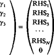
Solve equations. Specifying the boundary condition for each (i = 1—» N) of the collocation points results in N linear algebraic equations with the unknowns y, (/ = 1 —» N + 1). The additional equation can be found by specifying the Kutta condition at the trailing edge:
Consequently the set of equations to be solved becomes

 a 12
a 12
a22
a32
[ dm aN2 1 0 0
The above set of algebraic equations has a well-defined diagonal and can be solved for Yj by using standard methods of linear algebra.
Calculation of pressures and loads. Once the strength of the vortices y, is known, the perturbation velocity at each collocation point can be calculated using the results for a vortex distribution (e. g. Eq. (3.147)):
Q’=(Q, J, + y,Yl+’ (11.106)
 |
and the pressure coefficient can be calculated by using Eq. (11.18):
The lift of the panel can be computed from this pressure distribution or by using the Kutta-Joukowski theorem
 (11.107)
where Acj is the panel length. The total lift and moment are obtained by summing the contribution of the individual elements (as in Eqs. (11.54) and
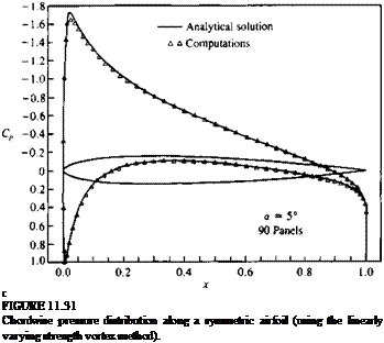
A computer program based on this method is presented in Appendix D (Program No. 6) and the computed pressure coefficients for the airfoil of Section 6.6 at an angle of attack of 5° are presented in Fig. 11.31.


