LINEARLY VARYING SINGULARITY STRENGTH METHODS (USING THE NEUMANN B. C.)
As an example of higher-order paneling methods using the Neumann boundary condition, the linear source and vortex formulations will be presented. Since the linear doublet distribution is equal to the constant-strength vortex distribution, only the above two methods will be studied. Here the panel surface is assumed to be planar and the singularity will change linearly along the panel. Consequently, the singularity strength on each panel includes two unknowns and additional equations need to be formulated.
11.4.1 Linear-Strength Source Method
The source-only based method will be applicable only to the nonlifting configurations and is considered to be a more refined model than the one based on constant-strength source elements. The basic six step procedure is:
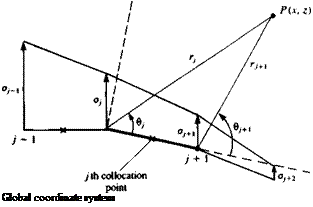
Selection of singularity element. A segment of the discretized singularity distribution on a solid surface segment is shown in Fig. 11.29. To establish a normal-velocity boundary condition based method (see Eq. (11.4)), the induced velocity formulas of a constant and a linear strength source distribution are combined (Eqs. (10.17) and (10.48), and Eqs. (10.18) and (10.49)). The parameters в and r are shown in Fig. 11.29 and the
where the subscripts 1, 2 refer to the panel edges j and j + 1, respectively.
zp +
|
x FIGURE 11.29 Nomenclature for a linear-strength surface singularity element. |
 |
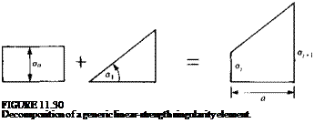
In these equations ct0 and a, are the source strength values, as shown in Fig. 11.30. If the strength of о at the beginning of each panel is set equal to the strength of the source at the end point of the previous panel (as shown in Fig. 11.29), a continuous source distribution is obtained. Now, if the unknowns are the panel edge values of the source distribution (ojt aj+1, . . . as in Fig. 11.29) then for N surface panels on a closed body the number of unknowns is N + 1. The relation between the source strengths of the elements shown in Fig. 11.30 and the panel edge values is:
af = a0 (11.88a)
Oj+i = o0 + axa (11.88b)
 |
where a is the panel length and for convenience the induced velocity equations are rearranged in terms of the panel-edge source strengths о) and ay+1 and the
subscripts 1, 2 are replaced with the j and / + 1 subscripts, respectively:
<?/(*/+1 – Xj) + (g/ + 1 – Oj)(x – Xj) r,
 4+1
4+1
—– 1 – u-z—- —fL + (6І+Л — в,)] in panel coordinates (11.89)
2n ‘*^y+i Гу/ L z j
![]()
![]()
Уiti+<’&«-*’> + ((( _„,
/’ r, 2jr(jfy+j – Гу)
in panel coordinates (11.90)
Note that Eqs. (11.89) and (11.90) can be divided into velocity induced by at and by oj+l, such that
(u, w)p = (ua, wa)p + (и*, wb)p (11.91)
where the superscripts ( )° and ( )b represent the contribution due to the leading and trailing singularity strengths, respectively. By rearranging Eqs. (11.89) and (11.90) the ( )° part of the velocity components is
and the ( )b part of the velocity components is
. – ■*<> JL – _L + (9 . „ ,1
2я{хі+і – Xj) ri+1 2nXj+l-Xj)l z J
To transform these velocity components back to the x-z coordinates, a rotation by the panel orientation angle a, is performed as given by Eq. (11.23):
This procedure can be included in an induced velocity subroutine SOR2DL (where L stands for linear) which will compute the velocity (и, w) at an arbitrary point (x, z) in the global coordinate system due to the yth element.
u, w
 ua, wa I = SOR2DL(a/( oj+u x, z, Xj, Zj, x.+1, zj+1)
The four additional velocity components (h“, wa, ub, wb) will be a byproduct of subroutine SOR2DL.
Discretization of geometry. The panel cornerpoints, collocation points, and normal vectors are computed as in the previous methods.
Influence coefficients. In this phase the zero normal flow boundary condition is implemented. For example, the velocity induced by the jth element with a unit strength Oj and cry+1, at the first collocation point can be obtained by using Eq.
(11.93) :
|
( |
u, w
ua, wa = SOR2DL(ay = 1, aj+^ = , xx, zu xh zy, xj+u zj+l) (11.93a) ub, wb I ij
where the superscripts ( )e and ( )* represent the contributions due to the leading and trailing singularity strengths, respectively. This example indicates that the velocity at each collocation point is influenced by the two edges of the y’th panel. Thus, when adding the influence of the j + 1 panel and on, the local induced velocity at the first collocation point will have the form
(и, w)! = (ua, Wa)na, + [(ub, w6)!! + (m“, H’a)12]a2 + [(иь, wb)l2 + (u“, *va)13]a3
+ • • • + [(иЬ, Wb)i, N-l + («“, *v<,)in]^n + (ub, wb)iNoN+l
This equation can be reduced to a form
(m, w)a = (m, w)!!^ + (m, w)12<t2+ • • • + (u, w)i N+laN+l
such that for the first and last terms
|
(a, w)„ = K, wOnOj |
(11.94a) |
|
(u, h01>;V+1 = (ub, wb)lNoN+1 |
(11.94b) |
|
and for all other terms |
|
|
(и, w)hj = [(и*, W’*)1>y_1 + (ua, Wa)hjOj |
(11.94c) |
|
From this point and on the procedure is similar to the constant-strength source method. The influence coefficient is calculated when ау = 1 and |
|
|
aij = (U, W)i, j ■ n, |
(11.95) |
|
For each collocation point there will be N + 1 such coefficients and unknowns |
Establish boundary condition (RHS). The free-stream normal velocity component RHSi is found, as in the case of the discrete source (by using Eq. (11.6b)), at the collocation point
RHS, = —1/«, sin a,
Solve equations. Specifying the boundary condition for each (i = —>N)of the collocation points results in N linear algebraic equations with the unknowns (j = 1 —* N + 1). The additional equation can be found by requiring that the flow leaves parallel to the trailing edge, thus
CTj + CT/v+^O (11.96)
Another option that will yield a similar result is to establish an additional collocation point slightly behind the trailing edge and require that the velocity will be zero there (stagnation point for finite-angle trailing edges). Consequently the set of equations to be solved becomes
Calculation of pressures and loads. Once the strength of the sources Oj is known, the velocity at each collocation point can be calculated using Eq.
(11.93) and the pressure coefficient can be calculated by using Eq. (11.18).
The formulation presented here allows for the nonlifting body to be “slightly” nonsymmetric. In the case of a symmetric body the number of unknowns can be reduced to N/2 (e. g., to the number of upper surface elements only) by the minor modification presented at the end of Section 11.2.1.
Note that for a closed body the sum of the sources must be zero. However, this condition is not an independent one and cannot be used instead of the additional equation (Eq. (11.96)).
A computer program based on this method is presented in Appendix D (Program No. 5) and the computed pressure coefficients for the airfoil of Section 6.6 result in a pressure distribution similar to that of Fig. 11.19.


