Main rotor power
It is now possible to combine all these improvements into a single relationship for the power required by a single main rotor (including an estimate of the effect of tip losses on the induced power), for example:
1 f 1
![]() Cp = L2XCT + — p3 — + p sCd(1 + 43p2) + Cpm + Cp,
Cp = L2XCT + — p3 — + p sCd(1 + 43p2) + Cpm + Cp,
CP — Cpj + Cppa r + CPpr + Cpm + CPs
where the subscripts represent: i – induced; par – parasite; pr – profile; m – Mach and s – stall.
 |
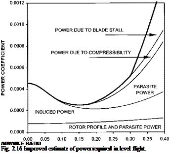
Figure 2.16 shows a more realistic variation of power coefficient with advance ratio.
Note how the induced power rises at high forward speed as larger disk tilts and higher thrusts are required to balance the drag. Likewise, note the significance of compressibility and blade stall at high advance ratio. These two factors are often combined under a single term ‘tip effects’.


