Off-design characteristics
The design of waverider shapes from known flowfields seems deceptively simple. We can imagine nothing aerodynamically simpler than generating lift in the way achieved by the caret wing at its design condition, with a uniform high pressure underneath and freestream pressure above, where at least the inviscid flow is an exact solution of the equations of motion. Yet a closer inspection of the flow reveals that its properties are not as simple as all that, even at the design point, and that they become quite complicated at conditions only just removed from the design point, although it may still be possible to solve the flow problem by small – perturbation techniques. If a waverider operates at conditions far removed from its design point, it loses all of its special properties and becomes, from the point of view of computation, no different from any arbitrary sharp – edged shape. The caret wing is again a suitable object of study to clarify and to classify possible flow patterns which may occur in various off-design conditions. Some knowledge of the types of flow to be expected should be helpful when interpreting experimental results and when we later discuss some theoretical approaches.
In these considerations, we can make use of some general properties of conical flows (see e. g. S H Maslen (1952), J W Reyn (1960), В M Bulakh (1962),
D KUchemann (1962)). In particular, we must refer back to the distinction to be made between nominally subsonic, sonic, or supersonic flows, which have been explained in section 6.3, equation (6.37). Further, it must be possible to recover the design solution as a special case of a more general calculation procedure.
Consider only flows where the shockwave is attached to the conically-supersonic leading edges of a caret wing and suppose that either some technique involving threedimensional characteristics or some finite-difference scheme were available to calculate the main part of the disturbed flow. Conditions to be satisfied include the boundary condition of tangential flow on the wing surface, and the oblique shock relationships at the outer edge of the flow.
Along the leading edges, where these two surfaces meet, both conditions must be satisfied: the freestream flow must be turned there parallel to the surface by the attached shockwave.
We can now consider a region around the leading edge, which is so small that we can assume the shockwave to be planar (and the surfaces to be plane with a straight leading edge on those shapes which are more general than caret wings). The problem is then equivalent to finding the flow over the lower surface of a yawed wedge. Consider a plane normal to the leading edge; the flow can be resolved into a component along the edge and a component in the plane with the incident Mach number Мд. In inviscid flow, the former has no effect since the wedge could be translated parallel to itself without changing the flow. The problem, therefore, reduces to that of solving for a stream with the Mach number Мд , to be deflected through and angle 6n (see Fig. 3.9). The angle on between the direction of Мд and the shockwave then follows from the cubic equation for oblique shockwaves, which involves Mn, on, and 6n, and is the same as for a twodimensional flow*. In general,
* Although this equation is well-known and may be found in many textbooks, its solution is tedious and often requires very precise calculations to ensure acceptable accuracy in the results. A computer program and charts prepared by J Pike (1972) may be used to obtain numerical answers.
we know that there will be either two, one, or no thermodynamically permissible solutions. If there is no solution, we must suppose that the shockwave is, in fact, detached. If there is one solution, then we suppose that the shock is about to detach. If there are two solutions, we may call them ‘weak’ and ‘strong’ by analogy with the corresponding twodimensional flow.
We define the weak solution as the one where the shockwave lies closer to the surface and causes the smaller entropy rise.
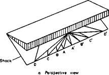
It is as well to observe here that the distinction between ’weak’ and ‘strong’ solutions is not absolute, but depends on which parameters of a problem are held constant. For example, consider the family of caret wings shown in Fig. 8.10, all of them formed from streamsurfaces of the same twodimensional
|
———- Strong solution for local flow ——— Weak solution for local flow |
|
b Conical projection Fig. 8.10 A family of caret surfaces derived from the same wedge flow |
wedge flow, and all supporting the same shockwave which would be judged ‘weak’ from a twodimensional viewpoint. However, if we were to adopt coordinates normal to the leading edge of one of the carets which has a very low aspect ratio (e. g. AA’ in Fig.8.10(a)), we should observe <5n to be small, and an to be large. We should then judge this same shockwave to be strong. There is of course no real paradox. Of the two possible shock solutions to the yawed-wedge problem, one is identified with the twodimensional shock of Fig. 8.10(a), and the nature of the alternative solution depends on the aspect ratio of the caret wing being considered. The situation is sketched in Fig. 8.10(b). For large aspect ratios (e. g. DD’ in Fig. 8.10(a)) the alternative solution lies outside the twodimensional solution; for small aspect ratios it lies inside. There is an intermediate aspect ratio for which they coincide. In measurements made specifically to test this point (Keldysh
(1969) ), it was found that the twodimensional solution always appeared, and the same conclusion is reached by analysing the results of Crabtree and
Treadgold (1966). Therefore, in these threedimensional flows, the strong shock solution can exist, but although there is no need to reject it, it does have a rather exceptional status, as we shall see below.
In the meantime let us note that the family of caret wings in Fig. 8.10 also introduces us to a classification of conical flows. When the shock as viewed from the leading edge is strong, the flow is conically subsonic (elliptic) in the whole contained region; whereas in the case of the weak shock, the flow remains conically supersonic (hyperbolic) near the leading edges and becomes conically subsonic only within a conoid from the apex (the parabolic surface) as indicated in sketch (b) of Fig. 8.11.

![]() (»)
(»)
(ь)
Fig. 8.11 Possible mixed-flow regimes
This leads us to a consideration of off-design patterns of mixed flows, in Fig. 8.11, for a succession of cases representing changes in anhedral angle, for which the flow is conically supersonic behind the leading edges and conically subsonic near the middle. Case (c) with zero anhedral is the flow over the lower surface of a plane delta wing*, for which a numerical solution has been given by D A Babaev (1962). The flow in the hyperbolic region has a velocity component on the surface, which is directed away from the centre line. The pressure is higher there than near the middle, and the pressure rise takes place in the elliptic region. D A Babaev finds that no discontinuity need be introduced near the parabolic surface, i. e. the air passes the sonic surface in a continuous manner. In case (a), however, the flow in the hyperbolic region has a velocity component directed towards the centre line, and the pressure is higher in the elliptic region in the middle. The
* In the present context, the plane delta wing may be regarded as a caret wing designed for the Mach number Mq = « .
shockwaves attached to the leading edges are initially still plane hut are closer to the surface than in the design condition, case (b). They do not intersect but are joined by what may be regarded as a strong and nearly plane wave in the middle, which is clearly visible in the shadowgraphs shown by L F Crabtree & D A Treadgold (1966). There has been some doubt as to how the pressure rise is accomplished by that part of the air which enters the subsonic region from the two supersonic regions. A simple conjecture (for an inviscid flow) has been drawn in Fig. 8.11(a), which includes two further discrete shockwaves and two singular points where three waves intersect.
This flow pattern has been observed by V N Alekseev & A L Gonor (1974), who not only confirmed the existance of the inner pair of shockwaves but also found that these may cause flow separations, in a manner as in Fig. 8.9, when these shockwaves are strong enough (e. g. when the angle of incidence is high enough). In all cases in Fig. 8.11, the supersonic flow does as it sees fit and follows simple rules; it leaves it to the subsonic region to adjust the flow and to straighten it out. In case (a), the shockwave has turned the flow too far in; in case (c), it has turned the flow too far out; when the turning is just right, we have the design conditions. Even though the possible types of flow on simple caret wings have not yet been fully clarified, we can say nevertheless that the prospect of finding satisfactory solutions to these mixed-flow problems appear to be much brighter than in the cases of transonic aerofoils and of supercritical swept wings, which have been discussed in section 4.8 and in Chapter 5, because of the constraints exercised by solid surfaces and because the flow tends to be uniform, at least in some regions. Furthermore, the transonic flow past aerofoils has features which make it difficult to use it in engineering applications, whereas mixed flow on caret wings does not appear to have these.
We can now attempt to summarise the various ■possible flow patterns over the compression surface of caret wings in a schematic diagram, showing only the main parameters a and Mq (numerical values for various examples may be found in L C Squire & P L Roe (1969), and see also L C Squire (1968)).
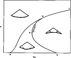
Fig. 8.12 shows the simplest and most natural version for caret wings with s/H-values of interest here, according to P L Roe (1972). The line SRQT signifies design conditions with a plane shockwave, the shock as seen normal
|
Fig. 8.12 Possible flow boundaries for caret wings |
to the leading edge being weak along SQ and strong along QT. Within the region to the right of SRQT the shock system lies inside the plane connecting the leading edges, as in Fig. 8.11(a). To the left, a flow regime exists in which the shockwave bulges outward, as far as a boundary PQ which corresponds to detachment conditions at the leading edge. To the left of PQ, no attached solution can exist. Above QT, although local attached solutions can be found at the leading edge, it seems impossible to calculate the remainder of the flow in a way compatible with them. Roe concludes that the shock detaches along the line PQT, but that the mechanism of detachment is different along PQ and QT. If the arc PQ is crossed from below, the shock detaches because it can no longer provide the required deflection. If the arc QT is crossed from below, the shock detaches because it is displaced by the inner shock moving out to the leading edge and beyond. With this interpretation, the attached shock at the leading edge is always weak, except along the arc QT of the design curve. On QT, although the flow has a very simple appearance, it is actually in a singular state of transition between two flow regimes.
Although this interpretation is plausible and self-consistent, it would be put on a firmer basis by careful measurements. Also, although it accounts for the geometry of relatively shallow, ‘wing-like’ caret surfaces, it is incomplete as regards very deeply anhedralled surfaces, for which special cases may exist where crossed shocks appear as described by J H L Venn and J W Flower (1970). These deeply anhedralled surfaces are relevant to controversies about the nature of minimum drag bodies at hypersonic speeds, as discussed by G G Chernyi (1964). Experimental data relating to such flows have been given by A L Gonor and A I Shvets (1967) and I C Richards (1976).
The various types of flow, which we have identified, may be expected to occur also on more complex shapes than the simple caret wing, but very little work of this nature has been done so far. We can also think of an odd situation where we arrange to have a weak shock along part of the leading edge and a strong shock along another part if the leading edge of a waverider, generated from a wedge flow, is highly curved. The initial generating shockwave is actually the same and 6n will stay the same for every point along the leading edge, but Mn will decrease. Such ‘mixed’ leading-edge shockwaves are the rule rather than the exception on waveriders generated from axisym – metric flowfields, as in Fig. 8.5. Nevertheless, J Pike (1968) found no abnormal behaviour in his experiments on cone-flow waveriders.
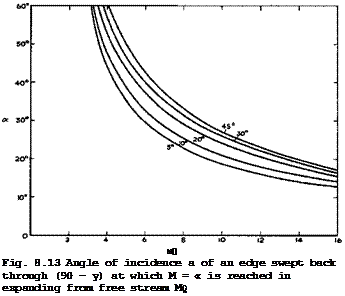
Even simple caret wings with attached shockwaves have upper surfaces which are no longer streamwise in many off-design conditions. Consider, therefore, what kind of flow pattern we can expect in such cases where the flows over the two surfaces are still independent of each other but where the mainstream is required to be turned downward over the upper surface. The simplest way of turning the flow over the leading edges is through a Pvandtl-Meyer expansion. A limit to this is set when vacuum is reached and the required turning angle cannot be achieved. But this is not likely to happen in most cases of practical interest, as can be seen from Fig. 8.13, where the angle of incidence of a sweptback edge is shown, at which M = °° is reached in expanding from the mainstream Mach number Mg. Good numerical answers for the expanding flow can be obtained from a computer program by J Pike (1972). The expanded flow is directed towards the centre line so that we are again faced with the question of how it can be turned back in the middle region, as in the flow past afterbodies in Figs. 8.8 and 8.9.
 |
The Aerodynamic Design of Aircraft
This problem occurs in its simplest form on the flat upper surface of a delta wing with nominally supersonic leading edges, set at an angle of incidence ot ; it has received much attention in this form. We can speculate that there should be a region of uniform conically supersonic flow inboard of the leading edges, as indicated in Fig. 8.11(d). A simple way of turning it back would be through a conical shockwave, the flow adjusting itself in the conically-subsonic, high-pressure region in the middle. This general flow pattern is consistent with that in Fig. 8.9 and also with the compressive flow patterns in Fig. 8.11. It is correct in a general way but not in detail.
Theoretical solutions for the supersonic flow past thin delta wings have been • given by L R Fowell (1956) and numerical solutions by D A Babaev (1962) who confirmed the existence of shockwaves (see also В A Woods (1970) and J Pike
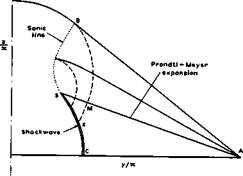
(1971) ). In this case, we also have carefully executed experiments by W J Bannink et al. (1965) and by W J Bannink & C Nebbeling (1973). In tests on a delta wing with s/SL = 1 at a = 12° and Mq * 2.9 , they found that the flow was essentially conical and did have a shockwave but that this was not strong enough to cause flow separation. A qualitative pattern of the conical characteristics is shown in Fig. 8.14 for a halfwing with the tip at A. The region of the Prandtl-Meyer expansion is now shown in detail, and the flow is uniform and directed inwards in the region AMKC. There is a shockwave CKS, which extends beyond the boundary characteristic BMK. The conical sonic line BS meets the shockwave at the point S where the strength of the shockwave tends to zero. The straight characteristics in the Prandtl – Meyer flow continue along curved extensions beyond BM and are reflected as compression waves at the sonic line BS. Thus, in the region between the sonic line and the boundary characteristic, there are expansion waves along one family of characteristics and compression waves along the other family. Across the characteristic AMS, the compression waves continue further along the straight characteristics in the region of conical simple waveflow and are eventually absorbed by the shockwave* There is also a good theory for calculating such flows, by P Kutler & H Lomax (1971), which allows shockwaves to
|
|
|
Fig. 8.14 Flow pattern over upper surface of delta wing. After Bannink and Nebbeling (1973) |
be found without a priori knowledge of their existence. Their results agree remarkably well with the experimental results of Bannink and Nebbeling, whereas Babaev’s numerical results are now considered to be inaccurate in some respects, such as the flow quantities in the region of uniform flow.
All these considerations hold when the flows over the compression and expansion surfaces are independent of each other, But matters become less simple when the lower shockwave detaches from the leading edges and is no longer contained between them. The subsonic flow around the sharp edges may then not be of the simple Prandtl-Meyer type but lead to a flow separation involving a vortex-sheet, as already discussed in section 6.3, Fig. 6.28. It is again convenient to describe the conditions in terms of the velocity components parallel and normal to the leading edge in the plane of the upper surface and to introduce the angle of incidence and the Mach number component normal to the leading edge:
A Stanbrook and L C Squire have analysed a large number of experimental data and concluded that the flow pattern changes from leading-edge separation to attached flow at a value of MN which lies between 0.6 and 0.8 at low angles of incidence and increases with angle of incidence. This holds also for wings with curved leading edges where conditions change along them. It would seem highly desirable to extend this investigation with a view to refining this rough categorisation.
We can now summarise the various flow patterns which occur on both surfaces of a lifting caret wing, designed to have a flow as in Fig. 8.11(c) at some values of s/A and Mq in the top right-hand region of Fig. 8.1, as the wing proceeds from low Mach numbers through sonic speed and supersonic speeds until its leading edges are conically supersonic. At the low-speed end, it will behave like a slender wing, as described in Chapter 6, with vortex-sheet separations from the leading edges, as shown in Fig. 3.6. The effects of anhedral on the development of the vortex sheets and on the forces, discussed in connection with Fig. 6.35, are particularly relevant in this context.
Just below Mq = 1 , a shockwave system will build up near the trailing edge, and there will be a noticeable upstream influence of a blunt base. As the leading edge approaches near-sonic conditions, a local supersonic region may appear above the now flattened vortex sheet, terminated by a shockwave, as shown in Figs. 2.13 and 6.28. A detached shockwave will form below the lower surface. As the mainstream Mach number is increased further, this shockwave will attach itself to the leading edges in the manner shown in Fig. 8.11(c) and a Prandtl-Meyer expansion will attach the flow to the upper surface, as indicated in Fig. 8.14. Eventually, the shockwave terminating the local supersonic region on the upper surface may be strong enough to separate the flow and to lead to a pattern as in Figs. 2.12 and 8.9. At the design condition, the contained shockwave over the compression surface will be plane as in Fig. 8.11(b), and the upper surface could be streamwise. The more complex shock systems in Fig. 8.11(a) over the lower surface and in Figs. 8.11(d) and 8.9 over the upper surface need not occur in normal flight and might be reached only inadvertently.
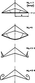
A remarkable feature of what might seem a rather complicated succession of flow patterns is that the changes in pressures, forces, and moments on the body are all small, gradual, and smooth. This has been demonstrated very convincingly in extensive experimental investigations by U Ganzer (1973) at subsonic, transonic, and supersonic speeds. Some of his results for a caret wing designed for Mq = 7 are shown in Fig. 8.15. This gives schematic flow patterns and pressure distributions over both surfaces at various mainstream Mach numbers for conditions when the upper surface is always streamwise.
These results fully confirm the conjectures and theoretical expectations we have about the types of flow which may occur.
There is a great variety of theoretical approaches for calculating the flows we have in mind. Some of the theories have already been mentioned, and we describe now very briefly some of the others which are relevant to our objective. A linear theory for delta wings with supersonic leading edges and with anhedral or dihedral has been given by R M Snow (1947). Pressure distributions are obtained in closed form. This theory can only apply when the product Mqci < 1 . Linearised theory in its standard form should apply only in off-design conditions when the Mach number is low enough for the Mach cone from the apex to lie well outside the leading edges.
A more elaborate theory for configurations with attached shockwaves has been developed by W D Hayes et al. (1961). Generally, the method of characteristics can be applied. A Frohn (1974) has extended the analytical characteristic method of К Oswatitsch (1962) to threedimensional flows, but this-has not yet been applied to lifting wings with supersonic leading edges. L C Squire (1965) has used the method of linearised characteristics in determining the flow past sharp-edged conical bodies; for extensive surveys of numerical methods of characteristics for threedimensional flows we refer to P I Chushkin (1968) and (1974). A L Gonor (1973) has reviewed theories of hypersonic flows
———– Upper turfocc

![]()
 ———– Lower surface
o y/s
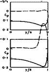 |
Fig. 8.15 Flow patterns and pressure distributions over a caret wing. After U Ganzer (1973)
past wings and paid special attention to caret wings; his survey must be regarded as an indispensable source of material in the present context.
Several other theories for waverider shapes have been discussed by P L Roe et at. (1971) and by L C Squire (1971). The theory of F Walkden & R H Eldridge
(1967) is a linearisation about the design condition. The shockwave is assumed to be attached and of the strong type. F Walkden & P Caine (1974) have given a solution for the flow past a specific thick non-lifting wing and also for a thin lifting delta wing with drooped leading edges, using a finite – difference technique (see F Walkden et at. (1974)). The results are much the same as those obtained by the shock-capturing technique of P Kutler & H Lomax (1971). In spite of the advances represented by these methods, it is usually required that the flow be supersonic everywhere, and a number of problems still remain.
There are some theories in which simplifying assumptions are made or empirical elements introduced, to predict pressures more rapidly than by the methods discussed so far. We mention here the work of В A Woods (1970), P L Roe (1971) and (1972), and M L Larcombe (1972) and (1973). J Pike (1972) has used the solution of R M Snow (1947) and applied it as a linear perturbation to the uniform design condition. The shock is assumed to be attached and of the weak type. W H Hui (1971) and (1972) also assumes that the shock is attached and treats the flow in the conically subsonic region near the centre line as one which differs only slightly from the twodimensional supersonic flow over a flat plate at the same angle of incidence as that of the lower
ridge line of the caret wing. The results of Pike and Hui are in good agreement with experimental results, and their methods may be regarded as reasonably accurate for simple conical wings. W H Hui (1973) has also investigated the effect of yaw on the flow over delta wings. An exact method for calculating the flow past caret wings with attached shockwaves at Mach numbers below the design value has been developed by U Ganzer (1975), following the numerical procedure of D A Babaev (1962).
What is needed for practical purposes is a theory which can not only deal with attached shockwaves but can also give adequate predictions of the detachment boundary (PQT in Fig. 8.12) and of the flow in the region beyond that. Such a theory is the thin-shock-layer theory which we shall now describe briefly, following a presentation by P L Roe (1972). This theory may be regarded as an extension of the simple Newtonian theory (equation (8.13), case (3)). In this, the flow behind a given shockwave becomes infinitely dense and the initial deflection of a streamline crossing the shock becomes identical to the local inclination of the shock itself, in the double limit M0 °°> Y 1 • The streamlines have no curvature in the body surface, i. e. they follow geodesics, or paths of shortest distance. Thus, each streamline, when it strikes the body, takes an initial direction in the surface such that the actual turning angle is minimised; thereafter, it follows that geodesic which passes through the initial point in that direction (see e. g. W D Hayes
(1958) , J P Guiraud (1960), J Pike (1972)). If the wing is conical, its surface is developable, i. e. it can be unrolled without stretching to yield a flat surface. The geodesics of a conical wing are, therefore, straight lines in the developed surface.
This leads to the model of the flow of thin-shock-layer theory, in which the shockwave and the body surface almost coincide and all the captured air flows in a very thin layer between them. As a numerical measure of how thick the shock layer is likely to be in a given problem, we may consider the density ratio є = Po/ps across some typical part of the shockwave, which should be a small quantity. This is given by
(y + 1)Mq sin^o
for a perfect gas, where о is the local shock inclination angle. Since the shock layer is supposed to be thin, we may take as a typical value of о the actual angle of incidence of the surface, so that
This quantity is always greater than 1/6 for air, and it is somewhat surprising that we shall find that results from this theory show useful agreement with experimental results even at very moderate values of Mq and a, when the allegedly small parameter є has a value close to unity.
Thin-shock-layer theory was originally developed by A F Messiter (1963) and has since been extended by К Hida (1965) and especially by L C Squire (1967),
(1968) , (1968), (1971) and (1974), who made it into a practical method, which can be used with confidence over a wide range of Mach numbers. Without going further into details, we know that, for conical wings, the pressure
distribution and the shock shape can be written as follows:
Cp = 2 sin^a (1 + ep(y/x)) , (8.20)
yg/x = є tan a q(y/x) , (8.21)
with є from equation (8.19). This shows clearly the theory as an extension of the Newtonian approximation. The two functions p(y/x) and q(y/x) depend on the cross-sectional shape of the body and are found by solving a rather complicated integral equation. Solutions for a wide range of conical wings with diamond, flat and caret cross sections have been presented by L C Squire (1968). R Hillier (1970) and (1972) has given results for wings with biconvex cross sections and for delta wings with general, non-conical, thickness distributions. He has also applied the theory to yawed wings.
V V Shanbhag (1973) has developed a fast computer program which is capable of determining the two functions for conical wings of any cross section at any given flight condition. In an extension of the method, L C Squire (1974) has shown how the accuracy can be improved in certain cases by using results from thin-shock-layer theory as a first approximation and then recalculating the flow with a more representative density ratio based on the shock shape found in the first approximation.
The problems in thin-shock-layer theory are well posed, especially for flows with detached shockwaves. For shock detachment itself, Squire’s modified theory gives the condition
![]() cos Ф
cos Ф
1——
є tan a
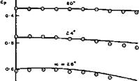
for flat conical wings. Squire’s results are compared in Fig. 8.16 with experimental results by L F Crabtree & D A Treadgold (1966) for a caret wing, where the test range lies very close to the detachment curve. Also, the test range cuts the design curve twice, at a = 16.2° and at 12°. The design point at 16.2° lies on the strong branch of the design curve and that at 12° is just on the weak branch. Thus both types of shock can exist in a real flow, and we find that the pressures are uniform at both points and agree with the values for the twodimensional flow past the generating wedge. At the higher angles of incidence, the shockwave is almost certainly detached. Squire’s theory represents the resulting pressure rise towards the leading edges quite well; the later modified version can be expected to fit even better. Thus this theory may be regarded as a useful design tool. What remain to be done are further extensions to non-conical flows and investigations of the conditions for leading-edge separations to occur behind detached shockwaves.
There is much support for the flow models assumed in these theoretical approaches from experimental investigations, many of which have already been mentioned. Pressures and shock shapes are generally of the kind predicted (see e. g. G H Greenwood (1970) and L C Squire (1971)), and changes in the type of flow when the Mach number is reduced to low-subsonic values have produced remarkably smooth changes in the forces and moments on waverider bodies (see e. g. U Ganzer (1973) and R F A Keating and В L Mayne (1969)). Whenever serious discrepancies between predictions and experiments have been found, these can be attributed to some effects of viscosity which will be discussed
![]()
The Aerodynamic Design of Aircraft
in section 8.4. Here, we refer to two examples where some discrepancies have been clearly apparent.
|
0-3 –
О Fig. 8.16 Pressure distributions over the lower surface of a caret wing |
One of these is concerned with the pressure distribution over the upper surface of some delta wings at the relatively low Mach number of Mq = 3.5 , where the shockwave is detached and stands off a long way and leading-edge vortex sheets result from a flow separation. J Szodruch & L C Squire (1974) have observed that a pressure rise near the trailing edge (which, on an aircraft, could be induced by trailing-edge flaps) can lead to bursting of the vortex cores and thus cause a complete change of the flowfield over the whole of the upper surface.
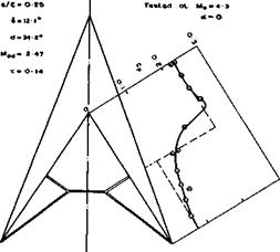
The other example concerns an off-design flow like that in Fig. 8.11(a). A caret wing was tested by L F Crabtree & D A Treadgold (1966) at its design angle of incidence but above its design Mach number. The results in Fig. 8.17 indicate the shock pattern, as deduced by means of a conical shadowgraph technique, by D Pierce & D A Treadgold (1964), and also the pressure distribution over the lower surface. A crude theoretical model of the flow may be constructed by assuming plane shockwaves attached to the leading edges, as in a twodimensional flow in planes normal to the leading edges, and then assuming the existence of oblique shockwaves which turn the inner flow into a direction parallel to the plane of symmetry. In the real flow, the two pressure levels are reached near the leading edges and near the centre line, but the discontinuous pressure change is smoothed out, perhaps in the manner indicated in Fig. 8.9. Similar results have been obtained in free-flight tests by J Picken & G H Greenwood (1965).
Previous Page
|
Fig. 8.17 Flow pattern and pressure distribution over the lower surface of a caret wing. After Crabtree and Treadgold |
There is as yet little information about the effectiveness of controls on waoeriders and about their dynamic behaviour. What there is suggests that this effectiveness is strongly dependent on viscosity, as will be discussed in section 8.4. Here, we mention the case of yawing motions where predictions based on the assumption of inviscid flow may give good answers, and where the generation of lift on compression surfaces by shockwaves may produce results which are quite different from those for wings where lift is generated by suction forces induced by vortex sheets over the upper surface. We recall that slender wings generally have an unstable rolling moment due to sideslip (see e. g. Fig. 6.55). The reverse may be true for waverider wings.
К Y Narayan (1974) has demonstrated experimentally that the perturbation in pressure due to yaw may be almost independent of the streamwise distance from the apex of the wing, so that pressures may be calculated on the assumption of conical flow, as in the theories of R Hillier (1970) and W H Hui (1973). Theoretical and experimental results for a gothic wing with a flat lower surface and for thin delta wings indicate that the perturbation due to yaw generates a stabilising rolling moment. But this may not be generally true for complete waverider configurations, as has been shown in extensive theoretical and experimental investigations by К Kipke (1973). If the moments are referred to the centre of the volume, Kipke’s results for several caret wings at Mach numbers between 6 and 10 show that the rolling moment as well as the yawing moment due to sideslip are statically unstable, although much less so than on slender wings at low speeds. Kipke has also investigated the effect of a central fin on the lateral stability; he finds that lateral stability can be achieved more readily at higher Mach numbers and when s/f £ 0.25 .


