VARIOUS WING ARRANGEMENTS
In the case of most single wing aircraft, the lift and performance are determined by analyzing the wing operating in the flow field as generated by the fuselage, and the tail operating in the wake of the fuselage and wing. A pair (or any number) of wings can be arranged so that they interfere or combine with each other. Configurations of this kind, such as biplane or tandem wings in particular, and related characteristics are considered as follows.
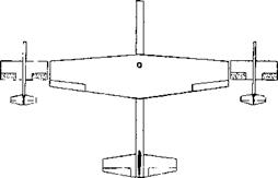
Tip-to-tip Coupled. When putting together two airplanes in flight, joining them by means of some mechanism at their wing tips, it can be speculated that their effective aspect ratio might be doubled and their range be increased, possibly to the /2 – fold. Actually, to keep each of these airplanes balanced without straining the coupling it will be necessary to deflect the ailerons, thus reducing the lift distribution approximately to that as when flying alone. Only when joining three airplanes together, as in figure 17, might the one in the middle really benefit. Considering what is said and presented quantitatively in Chapter VII of “Fluid Dynamic Drag” about flying in swept formation (as migratory birds do), it might be better to do just that, thus eliminating physical contact. The lateral stability problems described in (6) would then also be avoided. Of course, to transfer fuel two or more airplanes have to make physical contact somehow, but not for any long duration of time.
|
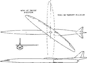
Figure 16. Oblique-winged configuration of a supersonic transport airplane. |
DYNAMIC (FORMATION-FLYING) MODEL OF A POSSIBLE TIP-TO-TIP COMBINATION OF A BOMBER WITH A PAIR OF FIGHTER
AIRPLANES. bQ = 1.1 m
b3 = 1.7 m
|
Aq = 5.1 A3 = 9.4
|
Figure 17. Arrangement of a bomber and two fighters coupled to each other.
Biplane. In the early years of aviation, hundreds of biplane-type airplanes were designed and built and they reached the peak of their development as fighter airplanes, particularly in England, between 1915 and 1925. Their aerodynamic characteristics were studied as a function of gap or height ratio, span ratio, stagger and so-called decalage (difference in angular setting as against each other). The optimum biplane (providing maximum L/D) has equal-size pannels. Many biplanes were developed, however, with a larger upper and a smaller lower wing (7,g). Theory indicates that in such configurations, aerodynamic efficiency is highest when the geometric aspect ratio of the upper wing is smaller and that of the lower wing is larger than the average. Since biplanes are hardly built any longer, except as sport or special purpose types, we will limit our presentation to that of the simple identical-panel type.
(6) Bennett, Tip-to-Tip coupled wings:
a) Bomber with Two Fighters, NACA RM L1951A12.
b) With Floating Fuel Tanks, NACA RM LI951E17.
(7) Theory and results of biplanes (multiplanes):
a) Prandtl, NACA T’Rpt 116, also Erg AVA Go III.
b) Munk, Bi – & Triplanes, NACA T’Rpts 151 and 256.
c) Knight, At High Angles of Attack, NACA T’Rpt 317 (1929), also TN 310, 325, 330 (1929).
d) Diehl, Engineering Aerodynamics, 1928 and 1936.
e) Griffith, Triplanes, ARC RM 250 (1916); many results as a function of height and stagger.
f) Noyes, Various Configurations, NACA T’Rpt 417.
g) Pressure distribution on one upper and Vi lower wing panel is reported in NACA T’Rpt 271 (1927).
h) Diehl, Relative Loading, NACA T’Rpt 458 (1933).
i) NACA, Load Distribution, Rpts 445 & 501 (1932/34).
![]()
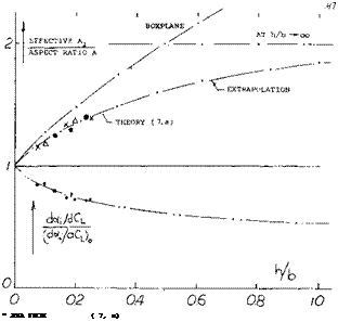
 A “boxplane” (having a pair of end plates connecting upper and lower lateral edges) has even higher ratios. Note
that the upper limit (for h/b…… oo ) is Ac /А = 2 for
the biplane, while for the “boxplane” A-JA……. oo.
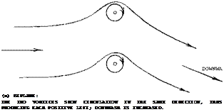
Lift Distribution. In part (a) of figure 19 a pair of lifting lines is shown representing a biplane. At the location of the lower vortex, the upper one induces a component of velocity against the oncoming flow. Vice versa there is such a component in the direction of the flow at the upper vortex. The average dynamic pressure is changed, accordingly. As a consequence, the lower wing of a biplane tends to exhibit somewhat less and the upper wing somewhat more lift, provided that both are set to the same angle of attack. Evidence for the difference is found in (7,b) where the combination of two panels each with A = 6 is tested at a gap ratio h/b = 0.1. The drag due to lift in the upper panel is found to be almost 20% higher, and that of the lower panel 20% lower than the average. For a certain lift coefficient, the loading can be made uniform by giving the lower wing a somewhat higher angle of attack (negative decalage). Another method is to give the lower panel a somewhat larger aspect ratio in a manner similar to that mentioned above. There are other considerations involved, however, in the design of biplanes, such as stalling for example.
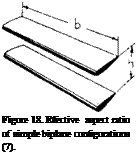
![]() Effective Aspect Ratio. The average induced lift angle of a monoplane wing is a function of the deflected volume of air and that volume corresponds to a cylinder of air having a diameter equal to the span V of the wing. Two identical wings far enough apart from each other have together two such cylinders, twice the volume and twice the lift, for a certain angle of attack but at the same induced angle of attack. Bringing the two wings together, in the form of a biplane, we may roughly assume that the cross section of the cylinder of air affected is that of two half circles with a diameter equal to ‘b’, plus twice the area between the two panels equal to 2(h b), where h = height or gap. We thus obtain tentatively
Effective Aspect Ratio. The average induced lift angle of a monoplane wing is a function of the deflected volume of air and that volume corresponds to a cylinder of air having a diameter equal to the span V of the wing. Two identical wings far enough apart from each other have together two such cylinders, twice the volume and twice the lift, for a certain angle of attack but at the same induced angle of attack. Bringing the two wings together, in the form of a biplane, we may roughly assume that the cross section of the cylinder of air affected is that of two half circles with a diameter equal to ‘b’, plus twice the area between the two panels equal to 2(h b), where h = height or gap. We thus obtain tentatively
Al/A= 1 + (8/TT) (h/b) (2)
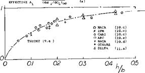
where A = b2 /S, and S = combined area of the two panels. Note that the value h/b = 0 represents a monoplane wing with twice the chord of the panels assumed. A more accurate analysis and experimental results are plotted in figure 18. The function can be approximated by
A-JA = (1 + 3.6(h/b))/(l + 1.4 (h/b) (3)
|
(b) GROUND EFFECT: THE GROUND IS SIMULATED BY AN IMAGE OF THE LIFTING VORTEX HAVING NEGATIVE LIFT; DOWNWASH IS REDUCED. |
Figure 19. Repiesentation of a biplane and of a wing near the ground, each by a pair of lifting lines.
|
|
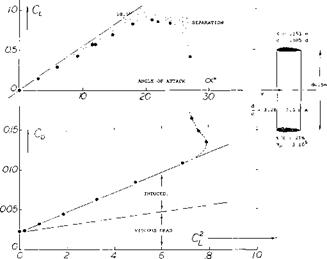
Figure 20. Lift characteristics of a ring-shaped airfoil (8,e).
Multiplanes. On the basis of constant span the induced efficiency increases not only as the height ‘h’ is increased, but also as the number of panels placed within that height is increased. Theoretically, the effective aspect ratio thus increases to that of the “boxplane” as in figure 18. The practical incentive for building biplanes or multiplanes is or was structural, compactness and maneuverability (rolling). A number of triplanes have actually been built and flown (2,a) over 50 years ago. Aerodynamic characteristics are reported in (7,e).
Ring Foil A ring-shaped “wing” such as in figure 20 is somewhat similar to a biplane. Analysis (8,a) concludes that the effective wing area of a ring is
S’ = 0.5 ТГ dc ^ 1.6 dc (4)
where (0.5 ТГ d) = half of the circumference. The equivalent stream of fluid deflected by such a wing is twice the cylinder defined by the diameter ‘d’ = 7Td/2. According to this theory, the induced angle of attack is less than half of that of a plane wing having the same span and developing the same lift. The effective aspect ratio is
A і = 2 d2/‘S’ = 4 d/(TTc) (5)
The induced angle is
dof /dCL = 1/(1ГАі ) = 0.25 c/d (6)
where CL is based upon the area S’ as in equation (4). The lift angle is
d«/dCL – (0.5/a TF) + (1/ TfAi ) (7)
The experimental results in figure 20 confirm this function when using the efficiency factor of the foil section a = 0.8. It must be noted, however, that the coefficients as plotted are based upon the area 2(d/c). Ring-shaped surfaces are sometimes used as stabilizing tails for bombs and similar devices. Ring foils are also discussed in the chapter on “small aspect ratios”. Accurate theoretical methods have been developed (8,g) for calculating the lifting characteristics. This method is based on the finite element method and given good correlation with experiment.
![]()
![]()


![]()
(8) Characteristics of ring-shaped foils:
a) Analysis by Ribner, J Aeron Sci 1947 p 529.
b) Muttray, Experiments, ZWB FB 824/3 (1941).
c) See also in the “small aspect ratio” chapter.
d) Dickmann, Axial Theory, Ing Arch 1940 p 36; see Brooklyn Poly Dpt. Aero Engg PIBAL Rpt 353 (1956).,
e) Fletcher, 5 Annular Foils, NACA TN 4117 (1951).
f) Milla, Lift and Drag Characteristics Biannular Wing Aircraft, JofA/C, Nov., Dec. 1966.
g) Carmichael, Finite Element Methods for Wing Body Combination, NASA SP-228,1969.
(9) Influence of ground on wings, theoretical:
a) Wieselsberger, AVA Gottingen Ergeb II (1923).
b) Datwyler, Wings Close to Ground, Mitteilung Aerody Inst., TH Zurich 1934; see ZFM 1933 p 442.
c) Analysis by Meyer, Hydrofoil Rpts 1950/51; and by Wu, Caltech Hydromechanics Rpt 26-8 (1953).
EXPERIMENTAL RESULTS:
0QATYYLER (9, b)
Л HOE. INER (10, b)
X DITTO UNDER CEILING
H/C,
7 ~2 3 4 3
Figure 21. Influence of the ground on the lift angle of airfoil sections in two dimensional flow.
![]()
![]()
![]()
![]()
![]() GROUND EFFECT. As far as the lift of an airplane wing is concerned, there are two effects through which the ground (of an airfield) affects the angle of attack necessary to produce a certain lift coefficient: the circulation of the airfoil section in two-dimensional flow is changed, and downwash and induced angle of attack are reduced. In case of the first effect, the height of the trailing edge above the ground is the parameter to be considered. Theory (9,b) predicts that roughly below CL = 1.5 lift will be increased in proximity of the ground, while above that coefficient with wing flaps deflected, for example, there will be a reduction of the sectional lift. Figure 21 presents results obtained in the range of lift coefficients (up to Cu = 1, where
GROUND EFFECT. As far as the lift of an airplane wing is concerned, there are two effects through which the ground (of an airfield) affects the angle of attack necessary to produce a certain lift coefficient: the circulation of the airfoil section in two-dimensional flow is changed, and downwash and induced angle of attack are reduced. In case of the first effect, the height of the trailing edge above the ground is the parameter to be considered. Theory (9,b) predicts that roughly below CL = 1.5 lift will be increased in proximity of the ground, while above that coefficient with wing flaps deflected, for example, there will be a reduction of the sectional lift. Figure 21 presents results obtained in the range of lift coefficients (up to Cu = 1, where
Cu(cx) is still linear). The lift angle da’/dCu
reduces considerably when approaching the ground, below h/c = 0.1. It must be realized, however, that there has to be a limit to the function plotted imposed by the fact that the trailing edge of the wing eventually touches the ground. When this happens, the pressure on the lower side is equal to the dynamic pressure (9,b) so that theoretically Cu# 1, at o^O.
|
ASPECT RATIO A _(dctf ±/йСь)h
|
|
|
0______________ L
0 2 4
I
|
|
Figure 22. Induced angle of attack of wings operating near the ground.
Induced Effect. Wings of conventional airplanes may never get close enough to the ground where the sectional effect as described above would become noticeable. For practical purposes, only the influence upon the induced angle of attack will then be left. The lifting-line equivalent to this ground effect is shown in part (b) of figure 19. While in a biplane the two vortices turn in the same direction, the ground is replaced by a mirror image of the lifting vortex. The plane of symmetry is characterized by the fact that no transport of air takes place across, as in the case of a solid plate. The influence of the ground upon the induced angle of attack (and drag) is presented in figure 22 in the form of the ratio
A/Ai=(dori/dCL)h/(d(y/dCL)oo (8) where h = height over ground measured to the wing’s quarter chord axis, and where ‘ oo ’ indicates conditions at h = oo. Note that the tangent near h/b = zero in part (a) of figure 22 indicated by d(A/A ) is twice that in figure 18 indicated by d(A /А). The two derivatives would be alike if defining for the ground effect 4T as the distance between the two lifting lines as in figure 19. The function as in figure 22 might be interpolated by
A/At = (33(h/b)Vi )/(33(h/b)y*+ 1) (9)
For conventional airplanes, when near the ground (taking off or landing), the height ratio can be between h/b = 0.1 and 0.2, (ЮДі) Figure 22 shows that at b/h = 10 the induced angle of attack is reduced to half. As to the spread of the experimental results in figure 23 (end plates), it can be said that on the average the more favorable points reflect the induced lift angle, while the less favorable ones indicate the drag due to lift. In this drag, there is usually a parasitic component involved due to interference on top of the viscous component of the airfoil section CmjnC* , which was always
subtracted when evaluating experimental results, mental results.
The reduction of the induced angle due to the ground may affect longitudinal stability and control of the airplane during the landing maneuver. In airplanes landing tail-down, the ground must also be expected to affect the horizontal tail surface directly. The ground effect will resist the effectiveness of the elevator in getting the tail down. The drag due to lift may not be of particular concern during landing. It is interesting, however, to speculate upon the reduction of drag to be expected when flying as close as possible to the surface. At an assumed h/b = 0.25′ or b/h = 4 the reduction of the induced drag is some 20% and that of the total drag (when flying at maximum L/D) is possibly 10%.
 Landing Flaps. As in swept wings where the wing tips are closest to the ground, Chapter XV, landing flaps can bring some portion of the trailing edge down to a small distance ‘h Here, as in wings, it might be better to define that distance from the 3/4 point of the “mac”. There is a good reason for selecting the three-quarter axis of the wing as the level of reference. Analysis (ll, a,b) shows that the effective angle of attack of the airfoil sections at the three-quarter point of the chord is really responsible for the lift produced.
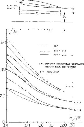
Ram Wings. So-called “Ground Effect Machines” or “Air Cushion Vehicles” have been investigated and built. One version of these vehicles, called “Ram Wing”, uses one or more wings with end plates or skegs attached to the lower side, thus coming very close to the ground or even slicing through the water surface. Figure 23 shows typical test results (12,e) of wings with aspect ratios of 1, 2 and 4 with and without end plates. Analysis of the induced angle is not readily possible because of the close proximity to the ground. The improvement with aspect ratio of the L/Dx is apparent from figure 23. The L/Dx also improves rapidly as the ground is approached and the end plates allow the main wing to operate further from the ground while maintaining high lift drag ratios.
![]()
Figure 23. Lift drag characteristics of a “ram wing” as a function of height above the ground.
(10) Influence of ground on wings, experimental:
a) See some references under (7).
b) Hoerner, Fieseler Water Tunnel Rpt 9 (1939).
c) See “due to lift” chapter “Fluid-Dynamic Drag”.
d) Reid, Full Scale Flight, NACA T’Rpt 265 (1927).
e) ARC, Experimental Results, RM 1847 and 1861.
f) Buell, On Delta Wings, NACA TN 4044 (1957).
g) Fink, 22% Thick A = 1 to 6, NASA TN D-926.
h) Baker, Ground Effect Low-aspect-ratio Airplanes, NASA TN D-6053.
i) Lockwood, Ground Effect Ogee Wing, NASA TN D-4329.
To provide longitudinal stability, two wings in tandem are used in (12,c). Analysis of pitching characteristics is simple, insofar as down wash (behind the first wing) is practically zero. When pitching, the height over ground of the first wing increases while that of the second one reduces. Within the small values of ground clearance investigated in (12,b, c) the section characteristics (such as the angle of attack for zero lift) change considerably. Also, when these vehicles are to be used over water the deformation of its surface (due to the pressure below the wings) must be taken into account.
(11) Wing theory:
a) Weissinger, Yrbk D Lufo 1940 p 1-145; ZWB Rpt FB 1553 (1942) see NACA TM 1553; Tech Berichte ZWB 1943; ZWB Rpt UM 1392 (1944); Math Nachrichten 1949 p 46; ZFW 1956 p 225; see NACA T Memo 1120 and TN 3476.
b) Pistolesi, 3/4 Chord Principle, Conf Rpt Lilienthal Ges Lufo 1937 p 214; applied by Weissinger (43,b).
(12) Longitudinal characteristics of “ram wings”:
a) Foshag, Ground Bibliography, DTMB Rpt 2179.
b) Harry, With End Plates, DTMB Rpt 1979 (1965).
c) Harry, Tandem Wings, DTMB Rpt 2259-1 (1966).
d) Low Aspect Ratios, See Chapter on this subject.
e) Lockheed study, Single and Tandem Low-Aspect Ratio Wings in Ground Effect, U. S. Army Trecom TR63-63.
|
Regarding downwash see Chapter XI dealing with “longitudinal stability and control”. The lift angle of the rear wing (in radians) is theoretically (da/dCL)2= l/(2atf) + (d«i/dCL)(l <£/<*0Cu/CL2) -(d‘£7dCu)(CL,/CL2)/(x/c) (10) |
![]()
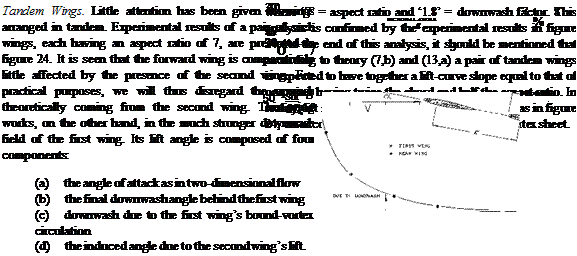 |
where є = final downwash angle (having a negative sign), where subscript ‘1’ indicates the first and ‘2’, the second wing, and where x = distance as indicated in the illustration. Note that in a tandem system using equal angles of attack CU1 is larger than C L2. • The last term of the equation covers the downwash component due to the first wing’s circulation. Replacing that wing by a bound vortex, the circulation velocity at the radius r = x is
w/V = – (0.25/тґ) CL)/(x/c) = – 0.08 CLj/(x/c) =‘£ ’ (11) where ‘£’ in quotation marks to distinguish this angle from the permanent or final downwash angle.. When considering the lift angle of the second wing, the angle ‘ C has to be multiplied with (Сиі/Сцг,). Therefore, m degrees:
d‘£VdCu= – 0.08 (180) (Cu/CL2)/TT(x/c) (12)
Also in degrees, the angle of the rear wing can be approximated by
(dor 5 /dCL = 11 + (20/7) (1 + 1.8 CL| /C(_2 )
+ (d‘fVdCL2.)
Figure 24. Interaction between a pair of wings operating in tandem (13,b).
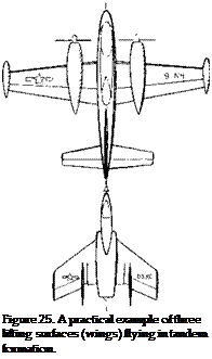
Tandem Wings – Refueling. Except for some special VTOL aircraft, few vehicles have been built with tandem wings. Thus, the mechanism given above becomes of interest only during special cases such as the refueling operation. One example is illustrated in figure 25. In this case the airplane being refueled is almost directly behind and is effected to a considerable degree by the downwash produced by the lead or tanker aircraft. In some cases where the tanker is large as compared to the refueled airplane, the downwash is the major factor. Refueling can also take place from a relatively small airplane such as the KC-135, figure 9 Chapter I, to a very large cargo airplane such as the C-5, figure 12. In this case the aft airplane can have a large effect on the tanker and the refueling boom. The supervelocity around the nose of the airplane can be particularly troublesome as the refueling boom must “fly” through this field to make contact with the airplane. The upwash produced by the aft airplane also gives a problem to the tanker, causing a nose-up change in trim (13,g). This can be a problem during the initial contact and breakaway maneuver.
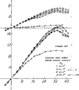
 shown on figure 27, there is little difference between lift curves for both the high and the mid vertical position canard arrangements up to an angle of attack of 16 . Above 16 the canard surfaces with increased leading-edge sweep develop higher values of lift with a corresponding increase in the total lift. When the wing and canard surface are on the same level the lift decreases. This reduction is due to the mutual interference of the two wings. On figure 27 the lift of the fore portion of the body without the canard surface is given. This was made possible by the dual balance system used. Characteristics of an airplane with a “canard” type of horizontal surface ahead of the wing are also presented in Chapter XI on “longitudinal stability”.
|
|
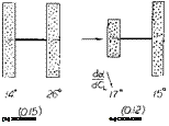
Canard Arrangement. Some experiments in (13,c) give more insight into the mechanism of tandem systems. A rectangular wing with A = 6 has a do( /dCL =14° when flying alone, and about 26 ,when in the rear position of a tandem system as in figure 26 (with an equal-span wing ahead). In the case of the “canard” arrangement (with the smaller wing forward) the rear wing is evidently receiving not only downwash, but also upwash (outboard the first wing’s span). As a consequence, its lift angle may possibly be as low as when flying alone. As tested, it is somewhat increased, id est to 15 , probably because of nonuniformity of the flow meeting the rear foil.
The effect of canard surfaces with variations of leading sweep angle, dihedral and vertical position (13,f) shows the mutual interference effects of the two wings. As
![]()
![]()
/4° ^0.075
Figure 26. Lift angle of tandem, and canard wing arrangements.
Figure 27. Effect of sweep and dihedral on the total lift of a canard airplane configuration.
(13) Characteristics of wings in tandem:
a) Glauert, Tandem Theory, ARC RM 949 (1923).
b) Luetgebrune, Wind-Tunnel Tests, ZWB FB 1677.
c) Eiffel, Resistance de Г Air & Aviation, 1919.
d) Cover picture, Aeron Engg Review Nov. 1955.
e) LePage, “Wing” plus “Flap”, ARC RM 804 & 886.
f) Gloss, Effect of Canard Leading-edge Sweep and Dihedral on Close Coupled Aircraft, NASA TN D-7814 d.
g) Aviation Week, Jan. 13, 1975.


