Wind coordinate systems
. Now the atmosphere thickens, and we take note of the air flowing over the vehicle. The air mass may be at rest or moving wrt the Earth. We assume, however, that it is monolithic, i. e., the air molecules remain mutually fixed. This characteristic qualifies the air to be modeled as a frame A.
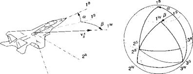
As the vehicle moves through the air mass, it experiences a relative wind over its body, which gives rise to aerodynamic forces. We introduce the wind coordinate system ]w. Only the Iw axis is defined unambiguously. It is parallel and in the direction of the velocity vector Vg of the c. m. of the vehicle В wrt the air A. The type of vehicle determines the other two axes. We distinguish between aircraft and missiles. An aircraft’s planar symmetry gives rise to the Cartesian incidence angles: angle of attack a and sideslip angle f, whereas missiles with rotational symmetry are frequently modeled by polar aeroballistic angles—total angle of attack a’ and aerodynamic roll angle ф’. We shall treat the TMs of wind wrt body coordinates for aircraft and missiles separately.
Cartesian incidence angles for aircraft. For aircraft the TM of wind wrt body coordinates [T]WB consists of two transformations with the interim stability coordinate system ]s. Unfortunately by convention, one cannot reach Jw from ]B by two positive transformations. The sequence is rather ]w ]v n with a negative alpha transformation (see Fig. 3.17). The stability system takes on a particular significance because both TMs [ T(a)ns and [T(f )ws are from its perspective reached by positive angles. Therefore, we first derive these individual transformations and then combine them to form (TWB.
The stability coordinate system is defined as follows. The Is axis is parallel and in the direction of the projection of the velocity vector Vg on the symmetry plane Is, 3B, and the 2s axis stays with 2B. The TM [TWB is about this 2s axis by the angle of attack a
cos a 0 —sin a
[T]BS =010
sin a 0 cos a
The second TM [7’]’vs connects with the wind axis through the sideslip angle f>
|
3B |
transformed about the 3 s axis
cos yS sin yS 0
[T]ws = — sin/J cos f) 0
0 0 1
![]() To arrive at our final destination, we multiply the two TMs but have to transpose first |T]B5, which has the effect of reversing the direction of the transformation,
To arrive at our final destination, we multiply the two TMs but have to transpose first |T]B5, which has the effect of reversing the direction of the transformation,

![]() cos a cos p sin p [7’]WB = —cos a sin p cos P —sin a 0
cos a cos p sin p [7’]WB = —cos a sin p cos P —sin a 0
This TM distinguishes itself by keeping the 3W axis in the aircraft’s plane of symmetry and aligning it with the 3 s axis of the stability coordinate system.
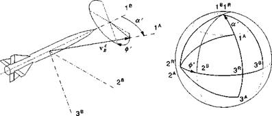
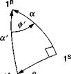
Polar aeroballistic incidence angles for missiles. For missiles with rotational symmetry, the load factor plane is more important than a body symmetry plane. It contains the total incidence angle a’ that gives rise to the aerodynamic force. As the stability axes subtend the aircraft symmetry plane, so does the aeroballistic coordinate system ]й line up with the load factor plane (see Fig. 3.18). In particular, the Iй and 3й axes lie in the load factor plane, with Iй coinciding with Iй. To change from the aeroballistic coordinates to the body coordinates, the aerodynamic roll angle ф’ determines the transformation ]в *^-]й about the Iй axis.
 |
Because the wind coordinates for missiles are different than for aircraft, we rename them aeroballistic wind coordinates with the label ]A. Their Iа axis is defined just like the 1w axis for the aircraft, namely it is parallel and in the direction of the relative velocity vector vAB but its 3A axis lies in the load factor plane, and the 2a axis remains in the 2B,3B plane. The transformation of the aeroballistic
coordinates wrt the aeroballistic wind coordinates [Г]*4 is by the total angle of attack а’, ]й <^—A, about the 2A axis. From the orange peels of Fig. 3.18, we deduct the TM of the body wrt aeroballistic coordinates
|
1 |
0 |
0 |
|
0 |
cos ф’ |
sin Ф’ |
|
0 |
—sin ф’ |
COS Ф’ |
and the TM of the aeroballistic wrt the wind coordinates
|
cos a’ |
0 |
—sin a’ |
|
0 |
1 |
0 |
|
sin a’ |
0 |
cos a |
Our goal is the TM of the aeroballistic wind wrt the body coordinates [ T ]AB. We get there in two steps. First, combine the two transformations (T]BA = [TriRTKA, and then take the transpose
j-j-jAB ___ j’j/JAj-j’jBB
![]() cos a’ sin a’sin 0′ sin a’ cos ф’
cos a’ sin a’sin 0′ sin a’ cos ф’
![Wind coordinate systems Подпись: [T]AB =](/img/3132/image105_1.gif) 0 cos ф’ —sin ф’
0 cos ф’ —sin ф’
—sin a’ cos a’ sin(// cos a’cos <p’
We have accomplished our task of deriving the TMs of the relative wind wrt the body coordinates for aircraft and missiles. If you compare Eqs. (3.18) and (3.19), you verify by inspection that they are not the same. Their transformation angles are dissimilar—Cartesian vs polar—and the wind axes are indeed defined differently.
From these TMs we can derive the definitions for the incidence angles in terms of the velocity components in body coordinates [йд]в — [и v w] and relative wind axes for aircraft дц w = [V 0 0] and missile [>g]A — [V 0 0], where V = vV + v2 + w2. The angle of attack a follows from the application of Eq. (3.18):
Kf =
|
V |
cos a cos fi sin/З sin a cos fi |
u |
||
|
0 |
= |
—cos a sin fi cos fi — sin a sin fi |
V |
|
|
0 |
—sin a 0 cos a |
w _ |
From the last line we derive
a = arctan (3.20)
To obtain a similar relationship for the sideslip angle fi, we use the two top lines V = и cos a cos fi + v sin fi + w sin a cos fi 0 = — и cos a sin fi + v cos fi — w sin a sin fi
![]()
|
|
 |
|
|
|
|
|
|
|
|
|
|
|
|
|
|
|
|
|
|
|
|
|
 |
![]()
![]()
|
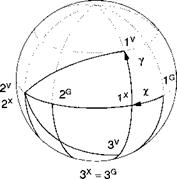
2V axis remains in the horizontal plane subtended by 1G and 2° (see Fig. 3.20). Two angles relate the velocity coordinates to the geographic system. The heading angle x is measured from north to the projection of vf into the local tangent plane and the flight-path angle у takes us vertically up to vf. The TM consists of the two individual transformations [T]VG = T (y )]VX[T (x)XG
|
cos у |
0 |
—sin у |
cos x |
sin/ |
o" |
|
|
0 |
і |
0 |
-sin/ |
cos x |
0 |
|
|
sin у |
0 |
cos у |
0 |
0 |
1 |
|
[TfG = |
 |
 |
||
and multiplied
From this TM we can derive the definitions for x and у. Let the velocity components in the geographic coordinates be [nf ]G = [uG vg u>g] and in velocity coordinates [uf]v = [f 0 0]. The TM of Eq. (3.25) provides the relationship [vEB]v = [T]VG[vllG
|
V" |
COS у COS X |
COS у sin X |
—sin у |
|
|
0 |
= |
-sinx |
cos x |
0 |
|
0 _ |
sin у COS X |
sin у sin X |
cos у |
|
UG Vg WG |
From the second line we glean
and you should also show that
![]() When you program these equations, you have to be careful with the arctan function because it is multivalued. Particularly, the heading angle can take on values from 0 to 360 deg. It is best to use the ATAN2 intrinsic routine that most computer languages provide.
When you program these equations, you have to be careful with the arctan function because it is multivalued. Particularly, the heading angle can take on values from 0 to 360 deg. It is best to use the ATAN2 intrinsic routine that most computer languages provide.


